![]()
( 1 of 1 ) |
Note to readers – this HTML document has been downloaded from the uspto.gov web site by the author/inventor and modified to be more readable
The entirety of this application, specification, claims, abstract, drawings, tables, formulae etc., is protected by copyright: 2013-2016 Donald L. Baker dba android originals LLC.
United States Patent |
9,401,134 |
Baker |
July 26, 2016 |
Acoustic-electric stringed instrument with improved body, electric pickup placement, pickup switching and electronic circuit
Abstract
An electric-acoustic stringed instrument has a removable, adjustable and acoustic artwork top with a decorative bridge and tailpiece; a mounting system for electric string vibration pickups that allows five degrees of freedom in placement and orientation of each pickup anyplace between the neck and bridge; a pickup switching system that provides K*(K-1)/2 series-connected and K*(K-1)/2 parallel-connected humbucking circuits for K matched single-coil pickups; and an on-board preamplifier and distortion circuit, running for over 100 hours on two AA cells, that provides control over second-and third-harmonic distortion. The switched pickups, and up to M=12 switched tone capacitors provide up to M*K*(K-1) tonal options, plus a linear combination of linear, near second-harmonic and near-third harmonic signals, preamp settings, and possible additional vibration sensors in or on the acoustic top.
Inventors: |
Baker; Donald L. (Tulsa, OK) |
||||||||||
|---|---|---|---|---|---|---|---|---|---|---|---|
Applicant:
|
|||||||||||
Family ID: |
55167201 |
||||||||||
Appl. No.: |
14/338,373 |
||||||||||
Filed: |
July 23, 2014 |
Prior Publication Data
Document Identifier |
Publication Date |
|
|---|---|---|
US 20160027422 A1 |
Jan 28, 2016 |
|
Current U.S. Class: |
1/1 |
Current CPC Class: |
G10H 3/22 (20130101); G10H 3/146 (20130101); G10D 1/085 (20130101); G10H 3/143 (20130101); G10H 3/187 (20130101); G10H 3/183 (20130101); G10H 2220/481 (20130101); G10H 2220/505 (20130101) |
Current International Class: |
G10H 3/18 (20060101); G10D 1/08 (20060101); G10H 3/22 (20060101) |
Field of Search: |
;84/726-728,742,743 |
References Cited [Referenced By]
U.S. Patent Documents
June 1932 |
Pfeil |
|
June 1933 |
Miessner |
|
January 1936 |
Lesti |
|
April 1941 |
Benioff |
|
December 1948 |
Fender |
|
June 1951 |
Morrison |
|
December 1960 |
Webster |
|
March 1961 |
Fender |
|
December 1968 |
Helbourne |
|
April 1972 |
Robinson |
|
November 1973 |
Wright |
|
October 1975 |
Rendell |
|
November 1975 |
Stich |
|
December 1979 |
Moog |
|
March 1981 |
Nulman |
|
September 1983 |
Sondermeyer |
|
April 1990 |
Clough |
|
February 1991 |
Pritchard |
|
December 1991 |
Valkama |
|
June 1997 |
Dodge |
|
October 1997 |
Jarowsky |
|
July 1999 |
Oteyza |
|
August 1999 |
White |
|
April 2000 |
Saul |
|
December 2000 |
Engard |
|
February 2001 |
Hendrickson |
|
February 2003 |
Erismann |
|
November 2003 |
Hartill |
|
October 2004 |
Sawhney |
|
June 2005 |
Childress |
|
January 2006 |
Small |
|
February 2006 |
Petersen |
|
June 2006 |
Spalt |
|
November 2006 |
Wu |
|
December 2006 |
Redard |
|
October 2008 |
Moghaddam |
|
November 2008 |
Redard |
|
April 2009 |
McGrew |
|
August 2010 |
Dahl |
|
July 2012 |
Zoran |
|
December 2010 |
Zoran et al. |
|
Other References
|
Primary Examiner: Donels;
Jeffrey
Claims
I claim the following, and
as a Pro Se inventor with limited resources request the help of the
Patent Examiner to state these claims correctly:
1. An
improvement for mounting electric vibration sensors in conventional
stringed instrument at any point on said instrument, comprising:
a. sensors for transforming the vibrations of body parts and strings of said stringed instrument into electric signals of an audio nature,
b. a plurality of paired and marked mounting points for said sensors in or on said face of said instrument, placed on opposite sides of said strings in the area between the neck and tailpiece of said instrument, near line positions perpendicular to said strings, said line positions placed near mathematical projections of the fret scale of said neck, called here virtual fret marks, visibly marked on the body of said instrument beside said mounting points,
c. a mounting and adjustment system, capable of placing said sensors in a plurality of positions and orientations in a cavity or a face of said stringed instrument, allowing for at least five degrees of freedom, based upon mounting plates containing a hole and a slot, said hole used to mount one end of said sensor via a spring and screw, with said mounting plate shaped such that said mounting plate can rotate about said sensor mounting screw at least 180 degrees relative to said sensor without interfering with the body of said sensor, said slot affixed either of said paired mounting points, with another of said mounting plates at the other end of said sensor, such that said sensor with a pair of mounting plates can rotate about and slide to and from said mounting points, and adjust in distance from said strings, whereby each of said ends of each said sensor can be moved independently toward and away from said strings, giving two degrees of freedom, and whereby each said end of said sensor can move independently along the direction of said strings, to positions between said neck and said tailpiece, giving two more degrees of freedom, and whereby each said sensor can move across the direction of said strings, perpendicular to a line between said neck and said tailpiece, giving one more degree of freedom, thereby allowing the player to choose and change the number, kinds and orientations of said sensors mounted upon said instrument.
2. An improvement as recited in claim 1, further comprising a marked scale in the direction of said strings, to one side of each line of said mounting points, on both the upper and lower surfaces of the body of said instrument, further comprising:
a. wherein any of said virtual fret marks is at a distance from said bridge of said instrument by a factor of one divided by two raised to the 1/12 power, approximately 0.943874, times the distance from said bridge to an adjacent virtual fret mark which is closer to said neck, or the adjacent last fret of said neck,
b. a plurality of distinguishing visible marks on said body to each side of said strings at virtual fret marks in each octave, further comprising:
i. lines at every virtual fret mark, until said lines are too close together to be legible and distinguishable from one another, and
ii. larger symbolic markings, corresponding to the traditional fret dots on said neck, until said markings are too close together to be legible and distinguisable from one another.
3. An improvement as recited in claim 1, wherein said mounting plates have one or more layers of vibration-absorbing material at contact points against said mounting points and said sensors, with cutaways to pass said screws and said connectors, to control unwanted conduction of undesired vibrations from said body to said sensors.
4. An improvement as recited in claim 1, wherein said mounting points are slides in tracks in or mounted to said body, to facilitate movement of said ends of said sensors along said strings, such that said slide can be held in a fixed position in said track by a mounting point screw, without bearing upon the bottom of said track, to hold said slide there by resulting friction.
5. An improvement as recited in claim 1, wherein said mounting plate further comprises:
a. a reinforcing ridge on the surface opposite said body of said instrument, with a cutaway about said mounting plate slot to pass the head of a mounting connector, and a cutaway to pass a head of a mounting screw for said string vibration sensor, also known as a pickup,
b. a reinforcing ridge on the surface toward said body of said instrument to guide and support said pickup mounting screw, whereby said ridges lighten and stiffen and strengthen said mounting plate.
6. An improvement to the body of a stringed instrument, comprising:
a. a plate-like and removable acoustic soundboard, also known as a top or top cover, mounted on the top surface of said body of said instrument, with the upper surface of said soundboard, away from said body, being a decorated surface, with a bridge assembly on said upper surface of said soundboard, which said mounting of said soundboard on said body allows acoustic vibrations across the entire surface of said soundboard, from interior to edges, except where said soundboard is fixed to said body,
i. being fixed to said body with removable connectors and adjustable in height above said body at two points adjacent to the neck of said instrument,
ii. being fixed to said body at and under a tailpiece,
iii. being fixed to said body with connectors in approximate line with said bridge at the sides of said body, said line called the bridge line or intonation line, an average of positions on said strings from said neck and the nut of said instrument to assure nearly correct intonation,
iv. having incorporated into said soundboard an electrostatic shield, over most of its extent, connected to the output ground of said instrument, for the purpose of shielding any sensors or electronics incorporated into said instrument,
v. with said bridge fixed to said soundboard between said soundboard and said strings for the purpose of adjusting the height of said strings above said soundboard, adjusting the intonation of said strings, and transferring the vibrations of said strings to said soundboard,
b. a tailpiece, with slots in the surface facing said bridge through which said strings of said instrument may pass, but the buttons on the ends of said strings may not, so that said strings are captured and positioned vertically and horizontally with respect to said bridge at the points where they exit said tailpiece, and with an electronic connection between said strings and said output ground of said instrument,
c. a decorated plate-like and removable bottom cover or back, fixed to said body with removable connectors, incorporating electrostatic shielding being electrically connected to said output ground of said instrument, wherein said soundboard vibrates independently from said body over much of its surface free of restrictions due to lack of connection at its edges to said body, allowing said body to vibrate at lower modes, wherein said soundboard and said bottom cover may be removed to gain access to any said sensors or electronics in said body, wherein said sensors and electronics may be mounted out of sight beneath said soundboard for the purpose of unobstructed decoration and improving or changing the timbre of said soundboard by removing the inertia and movement of said sensors or electronics.
7. The improvement to the body of a stringed instrument of claim 6 further comprising:
a. two screw plates placed on or in said body at the sides of said body, in line with each other and said bridge, with a series of threaded holes on said bridge line,
b. two bearing plates placed on the bottom of said soundboard, above said screw plates, with non-threaded holes aligned with said threaded holes in said screw plates, and with holes in said sound board, said non-threaded holes in said bearing plate and said sound board sized to pass the threads of adjustment screws,
c. two or more of said adjustment screws, having flat heads, screwing into each of said screw plates, pushing upwards against said bearing plates, providing at both ends of said bridge line independent control of the height of said soundboard, and hence said bridge, above said body,
d. two or more of adjustment screws passing through each side of said soundboard and each of said bearing plates, so as to hold said soundboard down against said flathead adjustment screws, whereby said adjustment screws and plates provide fine adjustments of the inclination along said bridge line and in the height of said bridge, independently at both sides of said body, and provide a means to eliminate rattle of said soundboard at said adjustment points with opposing pressures, and provide a means of bowing said soundboard upwards at said bridge to counteract sagging due to aging of said soundboard and string pressure, and provide a means to affect changes timbre by adjusting the resulting tension in said soundboard and by moving said adjustment screws to different positions on said screw plates.
8. The improvement to the body of a stringed instrument in claim 6 further comprising said bridge on said soundboard, situated vertically between said strings and said soundboard and horizontally between said tailpiece and said neck, closer to said tailpiece, over a cavity in said body, such that said bridge transmits vibrations from said strings to said soundboard, and such that said bridge adjusts the rough height of said strings above said soundboard, by means of removal of material from said bridge and an acoustically rigid spacing plate, otherwise known as the bridge base, between said bridge and said soundboard, with said bridge and said base mounted to said soundboard by removable connectors, and such that the intonation of said strings can be adjusted by removal of material from said bridge surface facing said neck, and by horizontal set screws in said bridge bearing upon said removable connectors to said soundboard, further comprising,
a. an upper part, otherwise known as said bridge, in contact with said strings on its upper surface, from which upper surface material may be removed to accommodate the radius of the frets and fretboard of said neck, and from which upper surface material can be removed in notches to affect string holding, rattle and position across said bridge at string bearing points on said bridge line, and from which upper surface material can be removed from said bearing points towards said tailpiece and said neck to reduce string rattle, and from which material may be removed from the upper surface of said bridge and the surface facing said neck to affect the individual intonation of said strings, with vertical slots at each end of said bridge, roughly parallel to said strings, though which said removable connectors pass, said slots roughly divided into equal parts by said bridge line, so that the average intonation of said strings can be adjusted by moving said bridge under said removable connectors in the direction of the neck,
b. a lower part, otherwise known as said bridge base, between said bridge and said soundboard, roughly uniform in thickness with holes situated roughly on said bridge line, underneath said intonation adjustment slots in said bridge, through which said removable bridge connectors pass into said soundboard,
c. said removable connectors, passing through said bridge and said bridge base into said soundboard, for the purpose of holding said bridge and said bridge base in position and correct intonation, and for removal of said bridge and said base without removing said strings,
d. said horizontal set screws, residing in said bridge slots roughly parallel to said strings, to bear upon said removable connectors, so as to affect the average intonation of said strings, and allow said bridge to be removed for the removal of material or replacement of strings, and replaced in the same position without changing the average intonation of said strings.
9. The improvement to the body of a stringed instrument of claim 6, wherein the soundboard is not fixed to said body between said bridge and the end of said body furthest from said neck, but instead is held to said body by the downward pressure of a removable and decorative tailpiece, further comprising:
a. a decorative and functional top part of said tailpiece, into which holes are fabricated to accept buttons of said strings, also known as the eyes of said strings,
b. slots fabricated to pass said strings from said buttons to said bridge while holding said buttons and said strings in place, and angled off the lines of said strings to prevent said strings from rattling in said slots,
c. at least one electrically conducting connection between all said strings and a point on said body for the purpose of grounding said strings to said instrument output ground, to reduce electrical noise and reduce static from the body of said instrument's player,
d. a decorative and electrically conducting hinge affixed to both said instrument body at the end furthest from the neck and said tailpiece top, part of the circuit to said ground, with a removable pin, such that an imaginary line between said pin and the points at which said strings exit from said tailpiece lies at an angle below the line of said strings from said tailpiece to said bridge, urging said tailpiece down upon said soundboard, providing a means to hold said strings in relation to said bridge and said neck, to conduct vibration from said strings to said soundboard, and to hold said soundboard against said body at that point, as well as to express the user's visual style.
10. The improvement to the body of a stringed instrument of claim 6, comprising a section of said soundboard, fixed by removable connectors to the edges of a box-like structure, otherwise known as an electronics compartment, containing batteries, electronics and controls, attached to the end of said body of said instrument furthest from said neck, otherwise known as the tail end, and a simple top-loading tailpiece, further comprising:
a. said top-loading tailpiece with a section on the vertical wall of the side facing said bridge tending away from said bridge, so as to keep or force said buttons of said strings downward towards said soundboard, with one or more vertical slots in said tailpiece, to accept said strings, sized and spaced so as to maintain the tendency in angle and spacing of said strings from said neck, while keeping said buttons of said strings from passing through,
b. removable connectors, i. passing through said tailpiece and soundboard into said body of said instrument, shortly behind said bridge, and ii. passing through said soundboard and said bottom cover into said edges of said electronics compartment,
c. said electronics compartment, covered on the top by said soundboard and on the bottom by said bottom cover, with removable connectors passing through said soundboard and said bottom cover into the edges of said compartment, said controls attached to and through said soundboard and the sides of said electronics compartment, with grounded electrostatic shielding incorporated into all sides of said compartment, thus allowing for more room between said tailpiece and said tail end of said instrument for said batteries, electronics and controls, and a mounting area on said soundboard which will be acoustically isolated by said removable connectors from the vibrating area of said soundboard.
11. The improvement to the body of a stringed instrument of claim 6 further comprising one or more other electronic vibration sensors attached upon it or incorporated within it to pick up other modes or timbres of vibrations in said soundboard at different points upon it, so as to offer the player more choices of sound.
12. The improvement to the body of a stringed instrument of claim 6 wherein said soundboard has side scallops, otherwise known as c-bouts, in close proximity to said bridge line, such that said soundboard is more flexible and able to carry vibrations from said bridge to the portion of said soundboard between said bridge and said neck, than said soundboard without c-bouts, whereby the acoustic output of said soundboard is increased.
13. An improvement to said soundboard in claim 6, wherein said soundboard has one or more fixed holes so that any of said sensors mounted within said body rise through said soundboard without making contact with said soundboard, for the purpose of positioning said sensors closer to said strings, without adding their mass and inertia to said soundboard, and thus inhibiting acoustic vibration.
14. A pickup switching system for electric stringed instruments that use electromagnetic coil sensors to sense the vibrations of ferrous-like metal strings, also known as pickups, so as to reduce the pickup of external electromagnetic noise from other sources, also known as humbucking, with two or more switched tone capacitors in parallel with the pickup output, comprising:
a. a pickup switching system that connects K single-coil pickups, all with equal numbers of turns in their coils, two at a time, such that when two of said connected pickups have opposite magnetic poles upwards, their signal outputs are connected together in phase, and when two of said connected pickups have the same magnetic poles upwards their signal outputs are connected together out of phase, producing (K*(K-1)/2) parallel-connected humbucking pair outputs and (K*(K-1)/2) series-connected humbucking pair outputs, for a total of (K*(K-1)) humbucking pair outputs, and for K greater than 3, a number of humbucking quad outputs from humbucking combinations of four of said single-coil pickups,
b. a switch of one or more poles and two or more positions, connected to two or more of said capacitors with one or more resistors of high value, typically one MegOhm or more, also known as bleeder resistors, across one or more of said capacitors, typically with the highest values of capacitance, to provide slow discharge of said capacitors to avoid switching noise, with one position which is not connected to any of said capacitors, with a potentiometer connected in series with said switched capacitance, to damp its effect, the resulting capacitance of said switched capacitance and potentiometer connected in parallel with said humbucking output of said pickup switching system, whereby said pickup switching system provides the instrument player at least (K*(K-1)) choices of humbucking outputs, such that in the instance of three of said matched single-coil pickups, it provides six humbucking pair outputs, such that in the instance of four of said matched single-coil pickups, it provides 12 humbucking pair, multiplied by the number of capacitor switch positions, wherein three of said single-coil pickups and a 3-position capacitor switch provide at least 18 choices of tone and timbre, and wherein four of said single-coil pickups and a 12-position capacitor switch, provide at least 144 choices of tone and timbre, plus the optional action of said tone potentiometer.
15. The pickup switching system of claim 14 wherein said matched single-coil pickups are designated as associated pairs, and connected together to assure humbucking by the functional equivalent of a double-pole, multiple-throw switch, such that one signal wire of one said pickup is connected to the high signal output, and a signal wire of the other said pickup is connected to the low signal output, otherwise known as the circuit ground in single-ended non-differential systems, leaving the remaining connections of said pickup pair to be switched, whereby the number of necessary switching poles for each said associated pair is reduced from four to two, generally in exchange for a lower number of humbucking connections than K*(K-1), where K is the total number of said pickups, such that:
a. in the instance of a number Knsp of said associated pairs with one north pole up and one south pole up, generally connected together so that their signals are in phase, said switching system can provide at least 2*Knsp humbucking connections within said associated pairs and Knsp*(Knsp-1) humbucking cross-connections between said associated pairs, and
b. in the instance of a number Knnp of said associated pairs with two north pole ups, generally connected together so that their signals are out of phase, said switching system can provide at least 2*Knnp humbucking connections within said associated pairs, and at least Knnp*(Knnp-1) humbucking connection between said associated pairs, and
c. in the instance of number Kssp of said associated pairs with two south poles up, generally connected together with signals out of phase, said switching system can provide at least 2*Kssp humbucking connections within said associated pairs, and at least Kssp*(Kssp-1) humbucking connections between said associated pairs, and
d. in the instance that said Knsp, Knnp and Kssp associated pairs exist in said switching system, it can provide at least 4*Knsp*Knnp plus 4*Knsp*Kssp plus 2*Knnp*Kssp additional humbucking connections between said associated pairs, and
e. in the instance of said associated pairs with the same pole up, if said pickups in one or more of said pairs are both reversed in signal polarity compared to at least one other of said pairs, said switching system may provide extra interconnections between said pairs, not calculated above.
16. The pickup switching system of claim 14 comprising circuitry for sequentially reducing the high-frequency peak or roll-off due to the resulting connection said humbucking pickup output with the resulting equivalent capacitance of said switched capacitors, by approximate steps of multiple fret units, M, otherwise known as factors of 2 to the power -M/12 in Western musical theory, comprising of:
a. said capacitors connected in series, connected to ground at one end of said series, with the switched terminals of said switch, commonly known as throws, connected at the junctions between said capacitors, with values of resulting switched capacitance chosen to approximate the equivalent capacitance to ground, necessary to facilitate said fret steps in frequency response,
b. two or more of said high value resistors, one connected in parallel with the grounded capacitor of said series, and the other connected from the other end of said capacitor series to ground, to inhibit electrical noise from the switching of said circuit, whereby the frequency roll-off steps produced by the circuit provides a monotonically increasing or decreasing progression to fit some desired rate and range of tone control, as determined by said factor M and the number of switch positions.
17. The pickup switching system of claim 14, comprising
a. said pickups connected via female plug connectors with at least three pins, the center of which is grounded, so the plug may be reversed, allowing reversing the phase of the signal of each said pickup, and
b. said switch connections of said pickup switching system are made via programmable cross-point connections on plug-in boards with physically shorted cross points, whereby the order and phase of switching said pickup pairs can be easily changed with new pickups, pickup positions and pickup signal phases, to accommodate some desired progression in tone and timbre with switching direction.
18. A system for amplifying, distorting or analog predistortion in an electrified acoustic and string instrument, comprising:
a. an anti-parallel diode pair for shaping the input signal, Vs, into an input-output signal transfer function, similar to an italic-f, which can be shifted with respect to the input with a bias voltage, Vb, providing a distorted output signal, Vd, with respect to said Vs and said Vb, Vd(Vs, Vb), such that an unshifted version of said Vd, Vd(Vs,0), approximates a combination of said linear signal, Vs, plus the approximate cubic of said linear signal, Vs.sup.3, and such that for non-zero values of said Vb, said Vd varies from said linear and cubic combination to a signal that approximates a combination of said linear signal, Vs, and its square, Vs.sup.2,
b. a mixer circuit which linearly and continuously combines said distorted signal, Vd, with the negative of said linear input signal, -Vs, so as to provide a predistorted output signal, Vdist, which varies continuously from a near-second harmonic of said Vs, Vs.sub.2, and to a near-third harmonic of said Vs, Vs.sub.3, with said Vs.sub.2 and said Vs.sub.3 respectively created by the cancellation of said Vs in said Vd, as it varies from said combination of said Vs and said Vs.sup.2 to said combination of said Vs and said Vs.sup.3, which Vdist is then combined with said Vs to create an output signal, Vo, which is a linear combination of said signals Vs, Vs.sub.2 and Vs.sub.3, which varies continuously in tonal character through said linear combination of said Vs, and its near-second and near-third harmonics, Vs.sub.2 and Vs.sub.3.
19. The system of claim 18 further comprising a multiple-gang potentiometer network to maintain the perceived amplitude of said Vdist within 6 decibels, by simultaneously controlling the level of said bias, Vb, the level of said Vd used by used by said mixer, and the levels of said Vs.sub.2 and said Vs.sub.3 provided by said mixer to produce said Vdist.
20. The system of claim 18, further comprising an automatic gain control, or AGC, which makes the amplitude of a duplicate of said Vs, which is used by said mixer to produce said Vs.sup.2 and said Vs.sup.3 and their linear combinations, constant over a range of at least 20 decibels in said Vs, such that said Vs.sup.2 and said Vs.sup.3 and their linear combinations are also constant in amplitude over said range of said Vs, and such that when said duplicate Vs is canceled from said Vs.sup.2 and said Vs.sup.3 by the mixer, said Vs.sub.2 and said Vs.sub.3 produced by said mixer are also constant in amplitude over said range of said input Vs.
21. The system of claim 18, wherein the circuit comprises separate diode pairs and mixers, in separate signal paths, to separately generate said near-second harmonic, Vs.sub.2, of said Vs, and said near-third harmonic, Vs.sub.3, of said Vs, such that for one given value of said Vs, all said signals and their linear combinations have amplitudes that produce similar perceived loudness in said output signal, Vo.
22. The system of claim 18, whereas the operating characteristics of said anti-parallel diode pair has an exponential dependence on the inverse of the operating temperature of said diodes, such that the control of said near-second harmonic and said near-third harmonic cannot be maintained over temperature changes, an embodiment of said electronic circuit in claim 18 wherein the component temperature of said anti-parallel diode pair is held constant by means of a resistive heater, comprised of:
a. a temperature measuring device thermally connected to both said diodes,
b. a heating device, thermally connected to both said diodes, to raise the temperature of both said diodes above the highest anticipated operating temperature of said diodes without a heater, as determined experimentally by said temperature measuring device, and
c. a controller to maintain the temperature of said diodes, said resistor and said temperature measuring device above said highest anticipated operating temperature, whereby the effects of said temperature dependence upon the character of said tonal and timbre output of said electronic circuit may be reduced.
Description
CROSS-REFERENCE TO RELATED APPLICATIONS
This
application claims the precedence of the related Provisional Patent
Application No. 61/861,800, filed Aug. 2, 2013, by this inventor,
Donald L. Baker dba android originals LC, Tulsa Okla. USA.
COPYRIGHT AUTHORIZATION
Other than for
confidential and/or necessary use inside the Patent and Trademark
Office, this authorization is denied until the Nonprovisional patent
application is published (pending any request for delay of
publication), at which time it may be taken to state:
The
entirety of this application, specification, claims, abstract,
drawings, tables, formulae etc., is protected by copyright: .COPYRGT.
2013-2015 Donald L. Baker dba android originals LLC. The (copyright
or mask work) owner has no objection to the facsimile reproduction by
anyone of the patent document or the patent disclosure, as it appears
in the Patent and Trademark Office patent file or records, but
otherwise reserves all (copyright or mask work) rights whatsoever.
STATEMENT REGARDING FEDERALLY SPONSORED RESEARCH OR
DEVELOPMENT
Not Applicable
NAMES OF THE
PARTIES TO A JOINT RESEARCH AGREEMENT
Not Applicable
INCORPORATION-BY-REFERENCE OF MATERIAL SUBMITTED ON A
COMPACT DISC OR AS A TEXT FILE VIA THE OFFICE ELECTRONIC FILING
SYSTEM (EFS-WEB)
No Known Applicability
STATEMENTS
REGARDING PRIOR DISCLOSURES BY THE INVENTOR OR A JOINT INVENTOR
Not
Applicable
TECHNICAL FIELD
This invention
relates to the body construction and electronic design of stringed
instruments, including guitars, sitars, basses, viols and in some
cases pianos, including the areas of: 1. construction of sound boards
on stringed instruments and control of their artistic and acoustic
properties (84/267); 2. adjustable positions of electromagnetic
transducers (84/276, 84/723, 84/726, 84/727); 3. the construction of
bridges and tailpieces (84/298, 84/299, 84/307); 4. the control of
the timbre of electromagnetic transducers by means of position
placement, combinatorial switching and analog signal processing
(applicable to any instrument that generates electronic signals)
(84/723, 84/726, 84/735)
BACKGROUND ART
The
Perfect Guitar
In the current state of the art, stringed
instruments are basically fixed in shape, appearance and function at
the time of manufacture or construction, with little or no ability to
make radical or even substantive changes to those properties within
the guitars themselves. At most, commonly available instruments can
usually change appearance only by refinishing the surface or using
appliques (U.S. Pat. No. 6,649,817) (or recutting the body, if
solid), and change the quality of sound only by changing the strings
and/or electronic pickups and circuits (if electric). It has been
written that some blues players screwed soda bottle caps loosely to
their acoustic guitars to create a harsher sound, which would horrify
a classical guitarist. Electric guitarists commonly change their
sound with exterior electronics, from mechanical reverberation to
buzz boxes to digital audio processors. All [are] subject to the
artist's taste, and artists may spend hundreds to thousands of
dollars to find their perfect guitar, which often is reserved for
just one of the styles of music and visual presentation the artist
employs.
Pickups: Mounting and Adjustment
Note
that the use of electric violins reportedly goes back to the 1920s
(see http://en.wikipedia.org/wiki/Electric violin), and U.S. patents
for electric violins go back to at least 1932 (see
http://digitalviolin.com/Patents.html), for example U.S. Pat. No.
1,861,717, which included an electromagnetic bridge pickup and a
skeletonized body. As early as the 1933 (U.S. Pat. No. 1,915,858),
Miessner patented an electromagnetic pickup based upon a set of wire
coils picking up the vibrations of strings near the static magnetic
fields of a number of pole pieces. In 1936 (U.S. Pat. No. 2,026,841,
Re20070), Lesti recognized that combining coils of opposite polarity
would cancel out extraneous magnetic fields, later called humbucking,
but used no permanent magnets in his pickup design. In 1948 (U.S.
Pat. No. 2,455,575), Fender patented a pickup based upon the same
physics as Meissner's, with a single coil. In 1951 (U.S. Pat. No.
2,557,754), Morrison patented a single-coil, six-pole guitar pickup
little different from those seen on guitars today.
As
early as 1961 (U.S. Pat. No. 2,976,755), Fender recognized that two
single-coil pickups with permanent magnets of opposite magnetic
polarity could be placed close together to cancel picking up exterior
hum. Note that side-by-side coils in a humbucker produce a
double-dipole field tends to reduce the reach of the field to the
strings. Many other patents have followed but are incremental changes
(Dave Hunter, The Guitar Pickup Handbook: The start of your sound,
Backbeat Books, Milwaukee Wis., 2008; not a critical reference, since
this patent does not cover a new type of pickup) to the three main
types of electromagnetic pickup commonly sold today: the single-coil
pickup, the humbucking pickup with two side-by-side coils, and the
humbucking pickup with two stacked coils. The single-coil pickup
tends to be the simplest, cheapest and easiest to produce, and can be
made at home. Other pickups include piezoelectric, capacitive, light
beam-interrupting LED and microphonic.
In most if not all
electric guitars on the market today, including unfinished bodies for
custom or home construction, have pickups placed in set positions,
with at most two degrees of freedom in adjustment from those
positions. The typical electromagnetic pickup can only be adjusted up
and down at each end. Wright (U.S. Pat. No. 3,771,408, 1973), claims
multiple mounting points for pickups, with three times as many pickup
mounting holes as the usual electric guitar, but merely shows three
separate pickups in FIG. 3, filling all the mounting holes, making no
other claim of adjustability. Another (U.S. Pat. No. 4,254,683,
1981), allows up and down motion on just one axis, with horizontal
motion between the neck and bridge.
Redard (U.S. Pat. No.
7,145,063 B2, 2006; U.S. Pat. No. 7,453,033 B2, 2008) has one of the
most complicated pickup mounting and positioning systems, offering at
most three degrees of freedom in positioning. Pickups in the system
below the strings (2006) move in one degree of freedom between the
bridge and neck, mounted on a set of parallel rods, with adjustment
screws specified to adjust the distance between the strings and
pickups. Both patents specify another pickup situated over the
strings, rather inconveniently for anyone who wishes to pluck or
strum them, moving on a track or bar parallel to the strings,
rotating in angle across the strings with a vertical elevation
adjustment above the strings, allowing three degrees of freedom in
position. While horizontal angular rotation above the strings changes
that orientation over the strings, it does not allow for alignment of
the poles across the strings. It can be rotated away from string 1,
the treble string, so that the pickup cannot appreciably detect
string 1 vibrations, without any means to correct it.
U.S.
Pat. No. 7,453,033 can claim four degrees of freedom, with adjustment
screws at the ends of the pickup. In U.S. Pat. No. 7,145,063, FIGS. 8
and 9 show an apparent double-coil pickup, shown explicitly in U.S.
Pat. No. 7,453,033, FIG. 3B, which is too far above the strings to
reliably detect their vibrations, especially for the double-dipole
field of that kind of pickup, which falls off faster with distance
than a single-coil pickup.
Spalt (U.S. Pat. No.
7,060,888, 2006) has a single pickup that rotates horizontally about
a fixed point under and beside the strings, allowing at most two
degrees of freedom, if it also rotates slightly in the vertical, or
can be adjusted vertically with washers on the pivot bolt.
Electric
Stringed Instrument Bodies, Especially Guitars
In the
area of body design, today's guitar market is dominated by acoustic
guitars of standard design (some of which have electric pickups and
amplifiers), electric guitars with solid bodies and electric guitars
with hollow bodies with wall and soundboard construction which is
considerably thicker and stiffer than acoustic instruments. Steel and
resonator guitars might be considered a subtype of either acoustic or
electric, depending upon amplification. Other non-acoustic stringed
instruments, such as autoharps, and lap steel guitars comprise a
small minority.
Some U.S. patents which address body
improvements that either radically change the appearance of an
instrument or allow an instrument's appearance to be radically
changed fall into some general groups: skeletal or wire-frame bodies
(U.S. Pat. Nos. 2,239,985, 3,413,883, 3,771,408); and modular bodies
(U.S. Pat. Nos. 3,657,462, 4,254,683, 4,915,003, 5,637,823,
5,682,003, 5,929,362, 5,945,614, 6,046,392, 6,194,644, 6,525,246,
6,809,245, 6,911,590, 7,002,065, 7,141,730, and 7,442,865). Of the
modular bodies, the large majority have a core section with the neck,
strings, pickups (if any), bridge and tailpiece (if any), where the
body attaches in one or more sections, with or without electronics.
One interesting variation (McGrew, U.S. Pat. No.
7,514,614, 2009) has a skeletonized body with an adjustable sound
board, connected to the body of the guitar at only three points.
However, the soundboard is constructed in several layers, including a
single "large magnetic transducer", impeding any vibration
of the soundboard that could contribute to the sound of the
instrument. The lever effect of McGrew's neck adjustments decree less
effect on bridge tilt than vertical adjustments in line with the
bridge. McGrew has no options for multiple sensors, adjustable in
position.
Zoran (US-2010/0307313 A1, 2010; U.S. Pat. No.
8,217,254 B2, 2012) describe a semi-skeleton body with a soundboard
top and electronics plugging into a central cavity. That soundboard
has an electronic plug at the neck end and two points of suspension
at the edges in line with the bridge, apparently held in place with
string pressure. It has no vertical adjustments at the edges to
counteract sag in the soundboard. Zoran describes sensors in the
soundboard to pick up different modes of vibration. The soundboards
of both McGrew and Zoran are limited in size and shape to the central
body cavity. They cannot be further decorated or shaped or stressed
to change the look of the entire guitar, or the major modes of
vibration. Zoran's instrument in particular requires a level of
manufacturing resources and expertise that precludes any major
physical modifications by a kit builder in search of personal
expression.
Electric Stringed Instrument Signal
Amplification, Control and Modification
Although in this
invention pickups may be mounted under the soundboard/top, through it
without touching, or upon it, mounting pickups under it drives the
need for an electronic pre-amplifier in the stringed instrument, as
the detected string vibration signal will be smaller, due to the
increased distance from standard pickups to the strings. Since many
musicians who play electric stringed instruments also use external
fuzz boxes, it makes sense to include such a feature in the preamp.
In this regard, U.S. pat. No. 4,1800,707 (1979), U.S. Pat. No.
4,405,832 (1983), U.S. Pat. No. 4,995,084 (1991) and U.S. Pat. No.
7,787,634 (2010) seem to be the most relevant.
Moog's
circuit produces "hard" and "soft" clipping to
get third and higher order odd harmonics by overdriving a
semiconductor transconductance amplifier, intending to replace vacuum
tube circuits. It obtains even harmonics, intending to produce
asymmetric waveforms, by using the same transconductance amplifier as
a "squaring" element to generate "soft" even
harmonics, and by a full-wave rectifier to generate "hard"
even harmonics. Combinations of which could be mixed with the linear
fundamental signal. Except for the more extremely asymmetrical
signals with even harmonics, the linear fundamental predominated. The
circuit largely maintained the character of the signal with automatic
gain control, or AGC.
Sondermeyer's circuit is a simple
diode clipper, which adds odd order harmonics, with a potentiometer
output which varies continuously between the linear fundamental
linear signal and the clipped signal, with some additional
band-shaping. In simulation, Pritchard's analog distortion circuits
produce various types of asymmetric clipping, with the linear
fundamental signal tending to predominate over the harmonics.
U.S.
Pat. No. 7,787,634 (Philip Young Dahl, 2010 Aug. 31) would seem to
interfere the most with the electronic circuit presented here. The
basic designs used both here and in Dahl's patent use concepts known
in other fields, such as microwave and laser communications, as
"analog predistorters", which date back to at least the
1980s. For example, RF Examples.pdf, circa 2004, from
http://cp.literature.agilent.com/litweb/pdf/ads2004a/dglin/dglin024.html,
speaks of using anti-parallel diodes and biased diodes to generate
Cubic Law and Square Law signals which are used for "eliminating
the fundamental".
Dahl's patent deals only with
distortion emphasizing the third harmonic. It controls the ratio of
the fundamental and third harmonic in the output primarily by
changing the amplitude of the input signal before clipping by
anti-parallel diode pairs. The remixing of the non-linear signal with
the inverse of the linear signal to produce the third harmonic occurs
only at a fixed gain. It does not then remix the third harmonic with
the linear signal to produce a continuous range from the linear to
the third harmonic to a predominately inverse linear signal after
generation of the third harmonic. Nor does it attempt to generate any
second harmonic signal.
Nor does it reduce the concept to
its simplest terms using the simplest circuit, which can be
demonstrated with an analog signal block diagram and associated
equations, and which will predict the widest possible range of
results, including emphasizing the second harmonic. It offers the
puzzling term "non-limiting clipping", which would seem to
be a contradiction in terms.
SUMMARY OF INVENTION
This
invention intends to provide a platform, a common canvas, for
combining musical expression and visual art in a stringed instrument
that is easy and practical to modify, manufacture and repair, even in
a home garage shop. It began and grew from a desire to create a
simple, lightweight guitar with a skeletonized body, using a neck and
one or more pickups from a used guitar. The pickups are intended to
be moveable in five degrees of freedom to any place, level and
orientation between the neck and bridge. A thin removable,
soundboard-top, was designed and intended for the placement of
artwork on a guitar, such that it could be embellished either by hand
or on a flatbed digital printer. The pickups could be mounted either
on it or under it, providing a surface uninterrupted by them. A
removable back, also separate of the size and shape of the guitar,
would allow access to pickups and electronics, and could be shaped to
the user's anatomy and playing style, with such things as the
belly-cut often found in solid-body electric guitars. It allows the
musician to change how the body of the instrument looks, feels or
sounds, piecemeal, without the expense of buying an entirely new
instrument. It allows the user to choose and switch the pickups, and
change the individual physical placement, height and orientation of
the pickups between the neck and bridge. It allows a choice of up to
12 different tone capacitors or none, and choice of linear or a range
of distorted outputs via on-board amplification. With
currently-available switches, it can produce up to 12 different
series and parallel connected humbucking pickup outputs from four
single-coil pickups. Electronic distortion control provides
continuous mixing of the output signal among the first, second and
third harmonics of the resulting guitar signal. Between that and 144
different pickup and tone capacitor switch combinations, it has
enough range in timbre to allow a musician to generate outputs
commonly perceived (see language example of U.S. Pat. No. 4,180,707,
Moog, 1979, cols 1 & 2) as varying from the warm, mellow tones of
jazz to the harsh tones of metal
(http://www.tulsasoundguitars.com/interviews-2/paul-humphrey-february-5-2-
014/). The thin and resonant soundboard-top and bridge, which is
cantilevered above the body, produces enough acoustic output to allow
quiet practice without electronic amplification. Two different
embodiments of tailpiece design offer a choice of a larger
cantilevered area of soundboard-top, to allow for more resonance and
acoustic output, or a top fixed firmly to the body below the bridge,
to allow for a larger stable area for electronic control placement.
Technical Problems Found and Resolved
In
development through several prototypes, various problems and
solutions presented and suggested themselves, leading to a more
complicated instrument. All the prototypes used commonly-available
necks, tuners, strings, electrical switches, electronic and
mechanical parts, and inexpensive single-coil pickups. The first
prototype had a single movable pickup, no soundboard and broke under
string pressure. The second had a volume control, two fixed pickups
and a two-piece Masonite top, cut and painted in the shape of a
barbed axe. Eventually two switches were added to provide serial and
parallel outputs, with a 12-pole choice of eight tone capacitors, no
capacitor, or three types of diode clippers.
The third
prototype worked, but was heavy and ugly with pickups that could not
be adjusted with the soundboard on. The fourth prototype is lighter,
but still heavy, allows its four single-coil pickups to be adjusted
by removing the bottom cover, and has an active electronic
pre-amplifier and distortion circuit driven by two AA cells. It has
10 different serial and parallel humbucking outputs, a choice of 11
different tone capacitors in parallel with the pickups with either
resonant peak or roll-off frequencies spanning almost three octaves,
and a choice of linear or distorted signal, with a distortion control
pot, for a total of 240 switch positions, plus a volume pot.
The
woodworking shop power tools have been limited those such as a drill
press, Dremel tool, Foredom flexible shaft machine, miter saw, table
saw, scroll saw and router table. This required an emphasis on
manufacture and repair at the level of a home garage shop, especially
using router templates and glued layers with alignment pins. Which
broadens the range of possible production to custom, production and
kit models, including models with bodies constructed from paper
plans, where the neck, musical hardware and electronics are purchased
separately.
In the process of this development, several
things became apparent. In order to produce the most string response
and acoustic output, a removable top could be fixed to the body only
at a few and widely separated point contacts. In the third and fourth
prototypes, this resolved to two at the neck and four in line with
the bridge, with the tail end of the body held down by a hinged
tailpiece under string pressure.
In order to put the
pickups as close as possible to the strings, while underneath the
soundboard, and to account for any sag in the soundboard under string
pressure, the soundboard has to be adjustable in height above the
body at both the neck and bridge line. At the bridge line, this
resolved to two screws at the edge of the body holding the soundboard
down on two flathead screws slightly closer to the bridge. At the
neck, this resolved to two screws close to the base of the neck
holding the soundboard to two narrow-diameter columns, made up either
of metal rods of adjustable height, or a stack of small washers. The
bridge on the third prototype was an inexpensive metal stop tailpiece
with adjustable intonation on each string. Because a loose metal
bridge part on it produced string rattle, the fourth prototype used a
shaped and filed wood bridge on an artwork base spacer, with set
screw intonation adjustments at the ends of the bridge.
The
second prototype used a 6 mm Masonite soundboard, and the third and
fourth used 6 mm, 3-ply Luaun plywood from a large chain home supply
store, simply because they are inexpensive, sturdy and readily
available. Other than the bridge, bridge base and bridge line screw
plates on the fourth prototype (including a thin brass plate under
the bridge to solder-mount the screws holding the bridge and base
down, the soundboards have no tuning or reinforcing ribs like thinner
acoustic instrument soundboards. For one thing, that would defeat the
option of putting the pickups as close to the soundboards as
possible. Yet the sounds they produce are credibly musical. Many
other materials and composites are possible, such as, fiberglass,
carbon fiber, metal, and Nomex or aluminum honeycomb. Perhaps wood
with carbon fiber inlayed into the top as both reinforcement,
acoustic control and visual art. Even soundboards with integrated
vibration sensors to replace electromagnetic pickups. It promises a
new field of design and experimentation.
The first and
second prototypes had no adjustable soundboards and used
commonly-available adjustable, non-tremolo metal bridges. As noted,
the third and fourth prototypes, with removable and adjustable
soundboards, used hinged tailpieces to hold down the tail of the
soundboard and allow it to shift with bridge line elevations. The
wooden tailpiece for the third prototype demonstrated that strings
could rattle in the exit slots of the tailpiece, which had to be
large enough to pass the string wraps securing the string-end button
to the string. This required a strip of hardwood to be added to the
bridge end of the tailpiece to confine the strings to narrow slots
passing non-wrapped string diameter. In the fourth prototype, the
tailpiece eliminated string rattle by canting the exit slots off the
line from the button to the bridge, so that the strings would bear on
one side of each slot.
The first prototype mounted a
single single-coil pickup mounted by standard springs and screws to a
narrow plate, which itself mounted, by screws and slots in its ends,
to smaller plates sliding in modified Nielsen-Bainbridge.TM. aluminum
picture frame moulding mounted to the skeleton body, providing
placement anywhere between the neck and non-tremolo bridge in a range
of height, and angular and cross-string orientations, beneath the
strings. In the third and fourth prototypes, two smaller plates
replaced the single plate. They each had a single hole for the
spring-and-screw pickup mount and a slot for the slide screw. They
allow a narrower body cavity than the single plate pickup mount. But
in practice, using slides in a picture-frame track proves to be
difficult to easily align with just two hands. So this invention also
specifies a set of fixed mounting points on the body, parallel to the
strings, with threaded holes placed in alignment with virtual fret
positions, extended from the neck towards the bridge, along with a
virtual fret scale inscribed in the body to index pickup mounting
positions and orientations.
The second prototype with
fixed-position pickups produced pickup from body microphonic noise
and required acoustic insulation in the pickup mount using a felt
material. In the third and fourth prototypes, cork and rubberized
auto gasket material were used on the contact points of the small
mounting plates between the pickups and the slides. The soundboard
vibrates more freely of the body compared to standard acoustic
instruments, where the soundboard is rigidly attached about its
circumference to the body. Because of this, this instrument is more
subject to acoustic feedback and ringing when placed in front of a
large amplifier-speaker set. Placed in front of a small amplifier, it
may produce a more pleasing reverberation. This reverberation, noted
in a Paul Humphrey interview video (cited above), may also be due to
some loose added windings to three of the four single-coil pickups.
Using inexpensive single-coil pickups to make up
humbucking pairs required that the coil turns be matched. A signal
generator driving a large solenoid coil with two pickups connected in
series and opposing inside. Testing each pair combination of coils
together this way determined the relative order of sensitivity to
outside magnetic fields. Turns were added to each of the three weaker
coils until their signals sufficiently cancelled the stronger coil.
Even using a do-it-yourself turning machine, these additional turns
tended to sit loose upon each pickup, and were held down with covers
of electrical tape to avoid excessive microphonics.
The
inexpensive, ceramic magnet, single-coil pickups tended to all have
the same magnetic polarity at the upper pole ends, usually North-up.
A very strong rare-earth magnet, rubbed back and forth over the
ceramic magnet, reversed the field on two of the four pickups used to
South-up, but perhaps not to the same level of intensity as before.
Because of this and the relative weakness of the pickup magnetic
field at the strings, when mounted below the soundboard as opposed to
on it, sets of small rare-earth magnets were added to the ceramic
magnets to boost the pickup fields. This patent does not preclude
mounting the pickups on the soundboard, or pushing up through holes
in the soundboard, to put the poles nearer the strings for a stronger
signal. But making pickup holes in the soundboard should be delayed
until the preferred pickup placement has been found. This can be done
with a half-soundboard that does not extend between the bridge and
neck, leaving the pickups uncovered and the strings resting on the
bridge.
Noise pickup from fluorescent lights also
required that the back-bottom cover have a grounded sheet metal
plate, that the pickups be covered with grounded aluminum foil under
the soundboard, that the strings be electrically connected together
at both ends and grounded through the tailpiece, and that the
electronics and controls be mounted either on or under grounded metal
plate. Ideally, electrostatic shielding shall be integral with the
soundboard, body and bottom cover to completely shield the pickups
and electronics.
In the fourth prototype, the electronic
controls and batteries were mounted on sheet metal plates to either
side of the hinged tailpiece, with a narrow section of soundboard
under the tailpiece between them. The electronics circuit board was
mounted to the pickup tracks in the body cavity under the soundboard.
A piece of aluminum flashing, shaped to the tail of the soundboard,
was grounded and mounted under the soundboard to provide shielding.
This arrangement, expedient for possible changes in the
electronics and controls, restricted the size and shape of the
soundboard from the bridge to the tail. It has been abandoned in the
patent plans for the fifth prototype, which specifies a soundboard
rigidly mounted to the circumference of an electronics compartment,
with controls in the compartment mounted to the soundboard, so that
the controls do not appreciably affect the acoustics of the
soundboard. This soundboard can be expected to have less acoustic
output, but is still free to vibrate from the bridge to the point
contact mounts at the neck. The body cavity has a cut-away section
under the bridge to facilitate soundboard vibration. The tailpiece on
the planned fifth prototype has been changed to a solid-mount,
non-hinge type and moved nearer the bridge, giving the electronics
compartment more room for controls. Thus the strings do not pull on
the tail end of the electronics compartment, allowing it to be made
of thinner and lighter materials. This also shortens the more massive
section of the body bearing string loads, to reduce body weight.
Ultimately, the pickup switching system derives from a
simple circuit with a DPDT switch which switches two pickups from
parallel to serial connections, with the in-phase lead of the pickup
with the North pole up (N-up) connected to one terminal of the
output, and the out-of-phase lead of the S-up pickup connected to the
other terminal of the output. The Figurers in the following Drawings
section show this to best effect. The fourth prototype uses two 4P5T
lever-operated "superswitches", sold by music parts houses
to replace the 5-way switch commonly used in electric guitars. The
simple circuit was doubled for this prototype, allowing four
dual-pickup humbucking and one quad-pickup humbucking circuit for
both parallel and serial connections.
In each of these
configurations, an N-up pickup is always paired with a S-up pickup.
Later, it became apparent in wiring a 3-pickup Fender Strat.TM. for
five humbucking pair outputs using a lever Superswitch, and then a
six using a 4P6T rotary switch, that it is possible to get outputs
for opposing-phase (out of phase or contraphase) humbucking pairs by
connecting two pickups with the same pole up. For this, the simple
circuit must be abandoned for all but two of the pickups, with
opposite poles up, requiring two switch poles for each of the other
pickups. This configuration naturally tends to minimize the
fundamental signal, leaving it with significantly higher levels of
harmonics, which is commonly perceived as either a hard rock or metal
music sound. If instead, the switching is wired to produce
quad-pickup humbucking outputs, the signal will have lower amounts of
higher harmonics and be perceived as warmer and much like an acoustic
instrument.
Eventually the switching network becomes more
complicated than available physical contact switches can easily
provide. For this reason, this patent specifies in FIG. 30, as an
example for a four pickup circuit, a 6P6T switch for a with an
inexpensive plug-in printed circuit board with solderable cross-point
connections. With one switch and a number of differently connected
cross-point plug-in boards, the full possible timbre range of the
instrument can be covered. A jazz player might want all the switch
positions to be series-connected humbucking circuits, pair and quad,
for warm mellow tones. An acoustic player might want mostly
quad-connected humbucking circuits. A metal rock player might want
mostly contra-phase connections and parallel-connected pairs using
pickups near the bridge to emphasize the higher harmonics.
The
electronic distortion circuits specified here derive from combining
the biased-diode circuit used in the fourth prototype with a circuit
installed in a Fender Bullet.TM. guitar near the beginning of 2008.
The Bullet circuit used an anti-parallel diode pair to generate a
signal with a logarithmic transfer function (much like Dahl, 2010),
and used the inverted linear signal to bend that curve down into a
quasi-cubic transfer function that emphasized the third harmonic over
the linear. At a certain signal level it inverted the signal peaks to
form clipping, like an over-driven tube amplifier. At higher levels
of distortion, determined by a pot, it pushed the peaks down past the
signal zero crossings, creating a harsh sound more useful metal rock.
The second harmonic is generated from a biased-diode signal, which is
similarly warped into a quasi-quadratic transfer function.
The
circuit shown in FIG. 49 was designed specifically to generate, for
one level of input determined by the setting of the preamplifier
Gain, three nearly equal and separate signals of the fundamental
linear signal, its second harmonic and its third harmonic. These are
then linearly recombined into an output signal, first by combining
the second with the third harmonic, then by that combination with the
fundamental linear signal. This required a 3-deck potentiometer, with
some complicated cross-calibration, but this can be and has been
eliminated by splitting the functions for generating second and third
harmonics into separate circuits, which are separately calibrated to
a given level of input signal.
BRIEF DESCRIPTION OF
DRAWINGS
More Details in the Description of Embodiments
FIG. 1--Skeleton body with pickup mounting system,
showing four single-coil pickups, two south pole up and two north
pole up, positioned under the strings along three octaves of extended
fret marks.
FIG. 2--Details of pickup mounting system
showing how the pickups are secured to the body by mounting screws,
slotted mounts with sound-absorbing material, adjustment screws and
springs. Both top and bottom mounting systems are shown.
FIG.
3A-E--Details of the pickup mounts used in FIGS. 1 and 2.
FIG.
4A-B--Details of an alternative track and slider pickup mounting
system with flat mounting plates, showing the two degrees of freedom
(DOF) of movement common to almost all electric guitars.
FIG.
5--Details of the alternative track and slider mounting system
showing the three additional DOF available.
FIG. 6--Top
view of the fourth prototype instrument, showing the artwork (Wolf
Head) soundboard, top mounting and adjusting screws, adjustable
bridge, bridge base, control mounting plates and knobs, neck, strings
and tailpiece. Some knobs are conceptual, not appearing on the
prototype as drawn.
FIG. 7--Side view of the fourth
prototype instrument, showing the top (soundboard), bottom cover,
upper, core and lower profile layers, and mounting details for the
soundboard, bridge and tailpiece.
FIG. 8--Detail of side
view with a vector force diagram (referenced to forces on the strings
at two points) showing how the strings force the bridge and tailpiece
down on the soundboard.
FIG. 9A-B--Back and bottom view
of hinged tailpiece showing construction details.
FIG.
10A-C--An alternative upper tailpiece hinge part made of molded or
extruded material, with string-capture slots and an optional
auxiliary bridge for intonation of sympathetic string vibrations
between the bridge and tailpiece.
FIG.
11A-D--Construction details of the fourth prototype bridge and bridge
base, showing the mounting and tension adjusting screws for the
soundboard in line with the bridge.
FIG. 12--Top view of
the instrument with a half-soundboard in place to adjust the
positioning of the bridge and pickups to achieve the desired string
height, intonation and timbre.
FIG. 13--FIG. 1 with the
neck removed and the bottom cover added, showing the neck mounting
area on the core profile, the prototype electronic circuit board
position, and the bottom cover electrical shielding under the pickup
and electronic cavities.
FIG. 14--The core profile.
FIG. 15--The lower profile.
FIG. 16A-B--Top
of the bottom cover (A) and Back of the bottom cover.
FIG.
17--Bottom view of the lower and core profiles, showing pickups using
the bottom mounting system.
FIG. 18A-B--Side and top view
of an alternative embodiment of the instrument, using a shortened
core profile, a top-loading tailpiece mounted by screws extending
through the soundboard into lower parts, a control box with more room
for electronics, and a different soundboard and bottom cover from the
previous embodiment, set up for three pickups with a five-way lever
switch.
FIG. 19A-B--Side and top view of alternative
embodiment with soundboard removed, showing a separate neck socket
and tailpiece base in place of an upper profile, a shortened core
profile, side walls, three pickups, and a single control box with
controls mounted on both the top right and left side to avoid
interference with picking.
FIG. 20A-B--Side and top views
of the alternative core profile, showing pickup mounting and
tailpiece base details.
FIG. 21A-B--Side and top views of
the alternative bottom cover, bottom cover electric shielding and
neck screw plate.
FIG. 22--The second prototype with a
metal bridge fixed to the body, showing different contact microphone
positions on the soundboard to get different timbres.
FIG.
23A-D--Introduces the basic circuit diagrams used here for pickups,
serial and parallel connections, and wiring details for double-pole,
double-throw switches to make those connections.
FIG.
24--Shows the 3*2 possible humbucking connections for three
single-coil pickups using a 4-pole, 6-throw (4P6T) switch, in series
and parallel, with signals aiding and opposed.
FIG.
25--Shows how a 6P6T switch is used to produce six series humbucking
pairs of four single-coil pickups.
FIG. 26--Shows how a
6P6T switch is used to produce six parallel humbucking pairs of four
single-coil pickups.
FIG. 27--Use of an existing 5-way
lever switch (4P5T) to produce five series humbucking outputs from
four pickups.
FIG. 28--Use of an existing 5-way lever
switch (4P5T) to produce five parallel humbucking outputs from four
pickups.
FIG. 29--Use of 4PDT switch to connect four
pickups to the 5-way switches in FIGS. 26 and 27 to produce 10
humbucking outputs, with the 12-position capacitor tuning-tone switch
and potentiometer attached directly to the chosen pickup output.
FIG. 30--A crosspoint matrix replacing series-parallel
connections directly on the pickup switch(es).
FIG.
31--Improved pickup connector and shielding.
FIG. 32AB,
33AB, 34AB--Show distortion circuits developed by inventor on Dec.
24, 2007 similar to those in U.S. Pat. No. 7,787,634 (Aug. 31, 2010).
FIG. 35A-B--Show the block diagram and transfer function
of the basic circuit that generates signal distortion based upon
mixing logarithmic and linear signals.
FIG. 36--Shows the
embodiment of the circuit in FIG. 35, as installed in the inventor's
guitar on or before Jan. 10, 2008.
FIG. 37A-B--shows the
simulated transfer function of FIG. 36, as the output versus the
guitar pickup signal.
FIG. 38A-B--Shows how settings of
the potentiometers in FIG. 36 can simulate 1960s tube amplifier
distortion in the guitar output signal.
FIG. 39A-B--Shows
how settings of the pots in FIG. 36 can produce an output dominated
by the third harmonic of the guitar signal.
FIG.
40--Shows the basic diagram for a circuit that can produce a much
wider range of simulated tube amplifier distortion, using a diode
bias voltage to change the operating point, and shift the transfer
function.
FIG. 41A-B--Shows the transfer functions and
signals for zero and maximum bias voltages.
FIG.
42--Shows the embodiment of the circuit in FIG. 40, as installed in
the fourth prototype guitar.
FIG. 43A-B--Shows the
simulated transfer function, input signal and output signal of FIG.
42 for zero diode bias.
FIG. 44A-B--Shows the simulated
transfer function, input signal and output signal of FIG. 42 for
maximum diode bias.
FIG. 45--Shows how to combine the
basic circuits in FIGS. 35A & 40.
FIG. 46A-B--Shows
the transfer function and output signal in FIG. 45, for controls set
to produce the linear input signal at the output.
FIG.
47A-B--Shows the transfer function and output signal for settings to
produce an output signal dominated by the third harmonic of the input
signal.
FIG. 48A-B--Shows the transfer function and
output signal for settings to produce an output signal dominated by
the second harmonic of the input signal.
FIG. 49--Shows
an embodiment of the basic circuit in FIG. 45, which is compensated
to minimize changes in output amplitude for changes in diode bias and
mixing of the linear and distortion signals.
FIG.
50A-C--Shows the estimated variation in maximum bias voltage in FIG.
49 with changes in battery voltage, and the transfer functions for
the non-linear voltage divider used in FIG. 49.
DESCRIPTION
OF INVENTION AND EMBODIMENTS BY MEANS OF FIGURES
FIGS.
1-5 Describe Body Improvements, Including the Pickup Mounting System
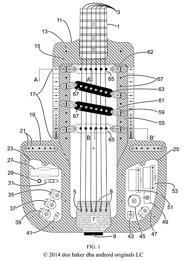
To illustrate the pickup mounting system, FIG. 1 shows
the 4th prototype with the soundboard (69, FIG. 2) removed and the
upper profile (11) visible. The neck (1), strings (3), string buttons
(5), tailpiece (7) and tailpiece hinge (9) show how the pickups (65
North up, 67 South up) can line up under the strings in the pickup
cavity (15). The pickups are attached to mounts (61) with height
adjustment screws (63) and springs (81, 82 FIG. 2). The mounts have
slots (62) for mounting screws (59).
In this embodiment,
the mounting screws are threaded into holes (57) in the body in a
deeper relief cut (55) below the top of the upper profile. They can
also be threaded into slides (97, FIG. 4A) fitted into tracks (95,
FIG. 4A). This arrangement allows both the pickup and mount to pivot
and slide so as to provide three more degrees of freedom (FIG. 5) in
adjusting pickup position under the strings. The holes (57) are
positioned in sufficient quantity and places that the pickups can
reach every position in between by moving the mounts.
Extensions
of the neck fret scale (17), up to three octaves, are inscribed on
the left and right of the upper surface of the body (11) to help in
positioning the pickups from the neck to the bridge (not shown, but
in line with 19 and 21), according to whatever musical theory or
preference the musician has. Theoretically in Western music, the fret
scale extends from the first fret or nut at the head of the neck to
the bridge, in steps such that each fret closer to the bridge by
2.sup.-1/12 times the distance to the fret next to it between it an
the head of the neck. If the neck is not fretted, then the fret scale
still exists as imaginary lines, or finger positions. The physics of
actual vibrating strings causes deviations requiring adjustments
called intonation.
Frets are numbered by integers
increasing from head of the neck to the bridge. At the bridge, the
theoretical fret number is infinity, because the frets decrease in
spacing from the head of the neck to the bridge in this mathematical
progression. In this embodiment, the neck end of the fret scale on
the body starts with fret line 24, the second octave from the head,
and extends three more octaves to fret line 60 near the bridge. It
allows one to do things like pick 5th, 7th and 12th root spacings
between the pickups, or between the midpoints of humbucking pairs. Or
to set up atonal spacings for metal rock music.
In other
features in FIG. 1, the screw plate and mounting screws for the
soundboard adjustments at the bridge line (FIG. 11) sit in cavities
(19) in the upper profile. The left electronic cavity (23) contains
the battery pack (27), the LED power indicator (29), the DPDT slide
switch for the batteries (31), the Bias (35), Warp (37) and Mix (39)
pots, and the Tube-Metal switch (41). These will be explained in
FIGS. 29 A&B. The right electronics cavity contains the DPDT
Linear-Distortion switch (43), the rotary 1P12T tuning capacitor
switch (45), the volume pot (47), the 4PDT series-parallel switch (49
and FIG. 28), the 4P5T lever switch for series connections (51 and
FIG. 26) and the 4P5T lever switch for parallel connections (53 and
FIG. 27).
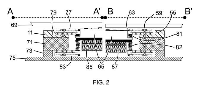
Depending
on what one deletes from the drawing, FIG. 2 shows the basic
arrangement of three possible mounting arrangements for the pickups
in their body cavity, top mount, bottom mount and a combination
top-bottom mount. Sections AA' and BB' from FIG. 1 show the pickup
mounting for different heights of the soundboard (69). Each one shows
the pickup (65) mounted below the soundboard, just far enough away to
avoid contact. Other pickups are possible, but this one shows a
ceramic magnet (85) style with a booster magnet (87) attached.
The
pickup is attached to the top mount plate (77) or a bottom mount
plate (83) with (non-magnetic) height adjustment screws (63), held in
place by either top mount springs (81) or bottom mount springs (82).
Should even more rigidity be desired, both mounts could be used. The
mounting screws (59) hold the mounts to threaded holes in the body
(11 upper profile, 71 core profile, 73 lower profile). Acoustic
insulating pads (79) on the mount plates are required to reduce or
avoid microphonic feedback. In this case, the mounts set in a relief
cut (55) in the upper profile (11), but another design might have a
complete removal of the upper profile in that area to mount directly
on the core profile (71).
The profiles themselves are
only a convenience to allow routing standard thicknesses of wood in
the fourth prototype. Any suitable material and method of molding,
subtractive machining or additive construction can be used. The same
applies to the soundboard and bottom cover (75).
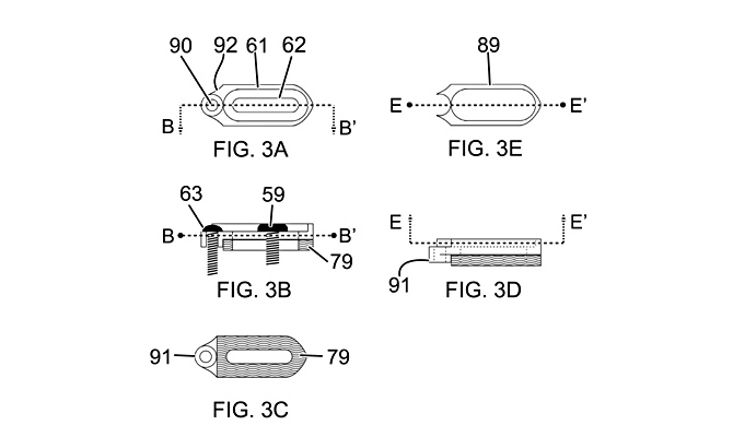
FIG.
3 shows details of one design of the mounting plate. Basically, the
mount is a flat plate with a hole (90) to pass or threaded for the
pickup height adjustment screw (63), a bevel or cutaway (92) to allow
the mount to rotate on the screw hole against the pickup, a slot to
pass the mounting screw (59) through to fix it to the body, and a
sound-absorbing acoustic pad (79) to avoid microphonic feedback to
the pickup. This figure shows possible embellishments to reinforce
the mount, a ridge (89) around the mounting screw slot and a collar
(91) around the adjustment screw hole. Section BB' goes vertically
through the long axis of the mount, and EE' horizontally through the
center of the ridge (89). Any suitable non-magnetic material or
construction process can be used to make it. The fourth prototype
actually uses 1/8 inch aluminum plates with two layers of gasket
material for (79).
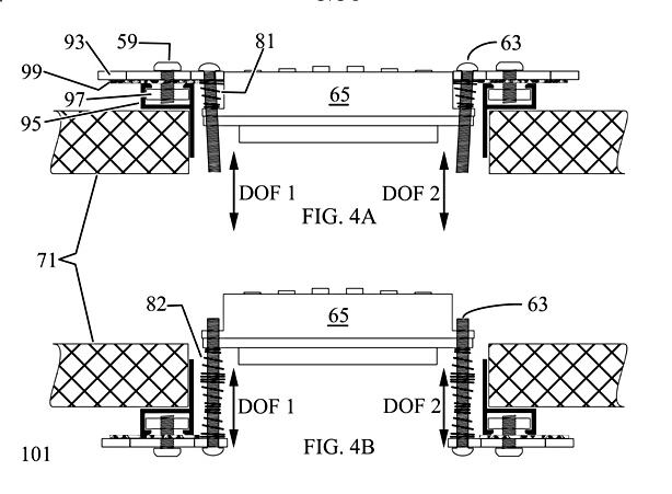
FIGS.
4 & 5 show an alternative track mounting system for pickups, as
well as the five degrees of freedom of pickup movement that either
mounting system allows. The pickup (65) is attached to the flat
mounting plate (93), with a sound-absorbing layer (99), by height
adjustment screws (63). Springs (81, top mounting; or 82 bottom
mounting) hold the pickup in position. The flat mounting plate is
secured to a non-magnetic track (95) by the mounting screw (59)
screwed a non-magnetic slide (97) captured in the track. The track is
secured to the body (71) on either the top (FIG. 4A) or the bottom
(FIG. 4B). The height adjustment screws provide a degree of freedom
of vertical movement at each end of the pickup (DOF1, DOF2). The
third prototype used the top mounting system in FIG. 4A, while the
fourth prototype used the bottom mounting system in FIG. 4B.
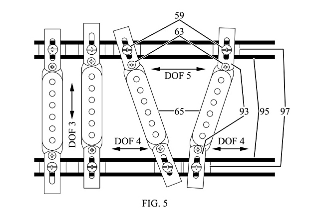
FIG. 5 shows how moving the mounts on the mounting screws in the
in their slots and pivoting the mounts on the height screws produces
movement perpendicular to the slots between them (DOF3), and along
the slots at each end of the pickup (DOF4, DOF5). In this manner, the
pickups can be placed anywhere along the length of the track which
can extend from the neck to the tailpiece, as it did in the third
prototype. However, pickups placed between the bridge and tailpiece
may tend to have little if any contribution to the output signal.
FIGS. 6-22 Describe Improvements to the Soundboard, Bridge and
Tailpiece
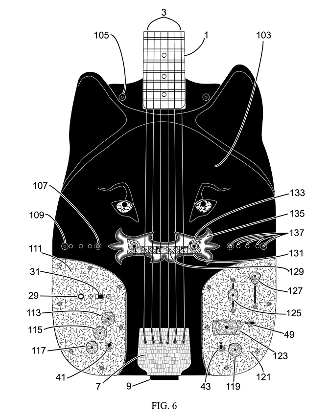
FIG. 6 shows one concept of an artwork soundboard, a black wolf's
head, used on the fourth prototype, which also has good acoustic
output. The soundboard (103) wraps around the neck (1), where it is
secured to the body by just two machine screws (105), threaded into
raised posts (13, FIGS. 1 & 7) directly, or with spacers (139,
FIG. 7)) on top of the posts. Strings (3) pass over the bridge (129)
to be secured in the tailpiece (7), which is attached to the body by
hinge (9). The height of the soundboard at the bridge (129) is
adjusted by flathead screws (107) below the soundboard, secured and
tensioned by bolts (109) with heads above the soundboard. Holes (137)
in the soundboard provide both passage for the top tensioning screws
and for an allen wrench or screw driver to reach the flathead screws.
The screws (107, 109) thread into the screw plates (21, FIG. 1).
The bridge sets on a decorative base (135) which also
sets the bridge height by its thickness. The bridge has slots (189,
FIG. 11A) through which non-magnetic screws (189, FIG. 11A) with
turning knobs (133) pass to tighten and secure the bridge and its
base to the soundboard. Set screws (131) threaded into the bridge
bear against these screws to set the position and angle of the bridge
with respect to the imaginary line corresponding to the base length
of the strings from the nut of the neck, where the fret number is
effectively infinity.
For the sake of ease of access to
the electronics during prototype testing, the controls are mounted on
a left plate (111) and a right plate (121) on either side of the
soundboard where the tailpiece holds it to the body by string
tension. This upper view shows the LED power indicator (29) and
switch (31), the Bias pot knob (113), the Warp pot knob (115), the
Linear-Distortion Mix pot knob (117), the toggle for the Tube-Metal
Distortion selection switch (41), the toggle for the
Linear-Distortion selection switch (43), the knob 119) for the volume
pot, the tuning capacitor selection switch knob (123), the toggle for
the Series-Parallel selection switch (49), the knob (125) for the
5-way series combination selection switch, and the knob (127) for the
5-way parallel combination selection switch.
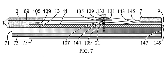
FIG. 7 shows the arrangement of profile layers from the side and
how the strings, bridge, soundboard and tailpiece interact. The
strings (3) pass over the neck (1) and the bridge (129) to be secured
in the tailpiece (7). The tailpiece is secured to the soundboard (69)
by a hinge with an upper part (9) screwed to the tailpiece, a lower
part (147) screwed to the body (one or all of 11 upper profile; 71
core profile; and 73 lower profile), connected by a removable hinge
pin (149). The tailpiece also has a grounding plate (145) for the
strings, and a base (143) to keep the metal parts from contacting and
marring the soundboard.
This side view shows the
soundboard secured by a round-head machine screw (105) through a
height spacer (139), threaded into a mounting post (13) extending
through and fixed in the upper and core profiles. The bridge assembly
(133, 131, 129, 135) sits on the soundboard. The bridge line
soundboard adjustment assembly (107, 109, 21) includes a bearing
plate (141) on the underside of the soundboard for the flathead
screw.
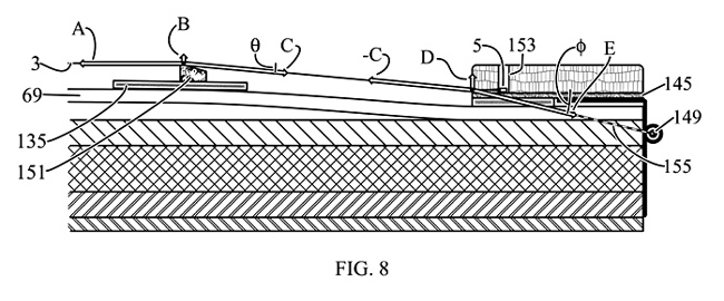
FIG. 8 shows the cross section (151) of the bridge, bridge base
and tailpiece at a string (3), and how the physical arrangement
produces force vectors A, B, C, D and E to demonstrate the downward
forces of the string on the bridge and tailpiece. The downward forces
opposing B and D achieve three things: 1) the strings bear down on
the bridge with enough force to ensure that string vibrations will
drive the soundboard to produce acoustic output; 2) the force of the
tailpiece against the soundboard removes the need for screws at that
end; and 3) the soundboard is then free to slide under the tailpiece
as necessary with changes in the height at the bridge.
The
string passes over the active part of the base where A, B, and C
originate. All the force vectors represent the forces at that point
on the string. A is string tension horizontally to the left. B is the
upwards force of the bridge on the string. C is the string tension at
angle -.theta. from the horizontal. Since the string is not moving
either vertically or horizontally from that position when at rest,
the vectors must cancel, or add up to a net zero in each of the
horizontal and vertical directions. The string exerts and equal and
opposite force to B downwards against the bridge.
The
string is secured by its button (5) in a hole (153) in the tailpiece.
We will ignore any forces between there and where it emerges from the
tailpiece. Where it emerges it encounters tension -C in the opposite
direction, .pi.-.theta., the upwards force, D, exerted by the
tailpiece, and a force E at direction -.phi. from that point to the
hinge pin (149). The force vectors -C, D and E must also cancel to
zero in the horizontal and vertical directions at that point. The
string exerts an opposite downwards force on the tailpiece at that
point, equal in magnitude to D.
Doing the appropriate
math produces two relations describing the magnitudes of B and D:
Math 1.
![]()
Math 2.
![]()
Math 3. If FA = 100, θ = 5º, and φ = 15º, then FB = 8.75 and FD = 18.0. As intended.
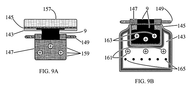
FIG. 9 shows an embodiment for the tailpiece and hinge assembly
from other views. FIG. 9A shows the previously described components
plus the screws (159) to attach the lower hinge (147) to the body. It
also re-identifies the upper part of the tailpiece as (157), which
not only holds the string buttons, but can be decorated by carving,
painting, etc.
FIG. 9B shows the bottom of the tailpiece
with the base mounted by screws (161) to the upper part (157) with
holes (165) to facilitate removal of the string buttons with a push
rod. The upper part of the hinge (9) is also screwed to the upper
tailpiece through the grounding plate (145), allowing the strings to
be connected to an electrical ground via the buttons contacting the
plate, contacting the lower hinge through the upper hinge and pin, so
that a grounding wire may pass through the body to be trapped under
and contacted to the lower hinge part.
The fourth
prototype was constructed in this manner, but other materials and
contacting methods are possible, so long as the strings are grounded.
Because not all the string buttons are assured to contact the
grounding plate (145), it was necessary to electrically interconnect
the string tuners on the head of the neck with brass foil.
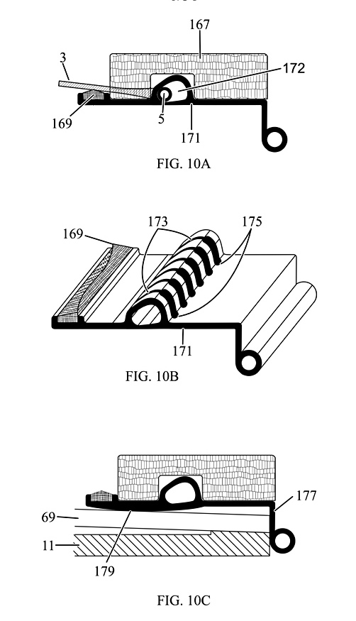
FIG. 10 shows an alternative embodiment for the upper part of the
hinged tailpiece. Here, the upper hinge part (171) is molded or
machined or extruded out of electrically conductive material. It
might include an optional secondary bridge (169) for intonation of
the strings between the bridge and tailpiece, since they do vibrate.
The cover (167) does not secure the strings, but is decorative. The
string buttons (5) are slid past entry slots (175) and are captured
against slots (173). The interior cross-section of this space (172)
is shaped to force the string buttons downward. This part (171) might
have a curved bottom (179) to allow different orientations of the
soundboard (69) against it.
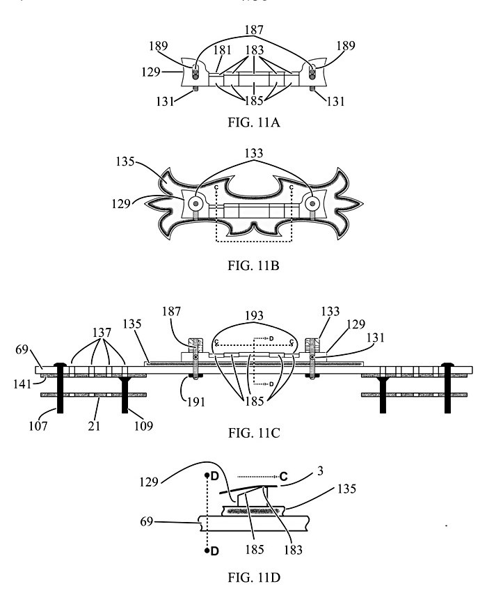
FIG. 11 shows more details in the construction of the bridge and
bridge line soundboard mounts on the fourth prototype. In this
embodiment (FIG. 11A), a wooden bridge (129) was cut for the fourth
prototype from 1/4-inch (6.5 mm) thick Purpleheart, an exotic
hardwood. Any suitable material and manufacturing process can be
used, even other types of bridges, such as metal tunematic bridges or
stop tailpieces. However the bridge parts of a tunematic bridge can
be prone to rattling. This approach eliminates bridge rattle while
allowing the musician to custom cut a bridge to a particular purpose,
tuning or style of music. The knob and screw tighteners (133, 187)
allow relatively quick changes to other pre-cut and adjusted (131)
bridges.
Here, the imaginary bridge line extends through
the bridge mounting screws (189). To avoid string rattle on the
bridge, it was necessary to cut away downward sloping areas (185)
behind the flats (183) upon which the strings rest. Intonation at the
bridge seemed to require only one cut (181) at the 6-string for
standard EADGBE tuning. A bridge base (135) serves as a shim under
the bridge to raise it to proper height, a decoration, and a
mechanism to transfer the acoustic energy of the strings from the
bridge to the soundboard (69). The bridge base in the fourth
prototype used 1/8-inch (3.2 mm) thick basswood cut to the design
shown (FIG. 11B).
FIG. 11C shows the previously described
bridge line mounting and adjusting assembly for the soundboard in
greater detail. In addition, it shows how the bridge is cut (193) to
accommodate the sting levels imparted or implied by the radius of the
frets and/or fret (or finger) board of the neck. This depicts the
bridge hold-down screws (187) threaded into nuts (191) secured to the
underside of the soundboard (69), with the knobs (133) permanently
attached to the screws. The fourth prototype used screws soldered
into the nuts, which turned out to be inconvenient for removing the
bridge. FIG. 11D shows how the back slope bridge relief cuts (185)
function under the strings (3).
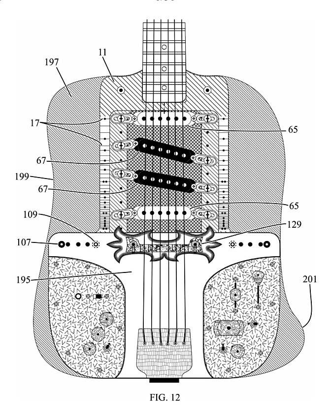
FIG. 12 shows how placement of the pickups (65, 67), adjustment of
the bridge (129), and the adjustment of the soundboard level setting
screws (107, 109) to achieve the desired timbres might be
accomplished with a half-soundboard (195). It also shows the bottom
cover (197), with a belly cut (199) and a thigh hook (201), adjusted
to the musician's needs.
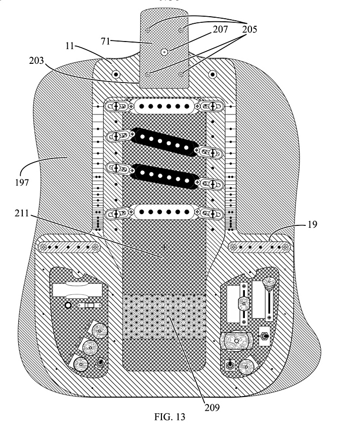
FIG. 13 shows the soundboard, neck, strings, and tailpiece
completely removed, revealing the part of the core profile (71) upon
which the neck is mounted, with holes (205) to pass neck screws (not
shown), and a center hole (207) through which a push rod can help to
remove the neck from the neck socket (203) in the upper profile (11).
The (fourth prototype) electronic circuit board (209) mounts to the
bottom of the core profile, and electrostatic shielding (211) covers
the bottom cover (197, and FIG. 16) under the lower profile (73, FIG.
15).
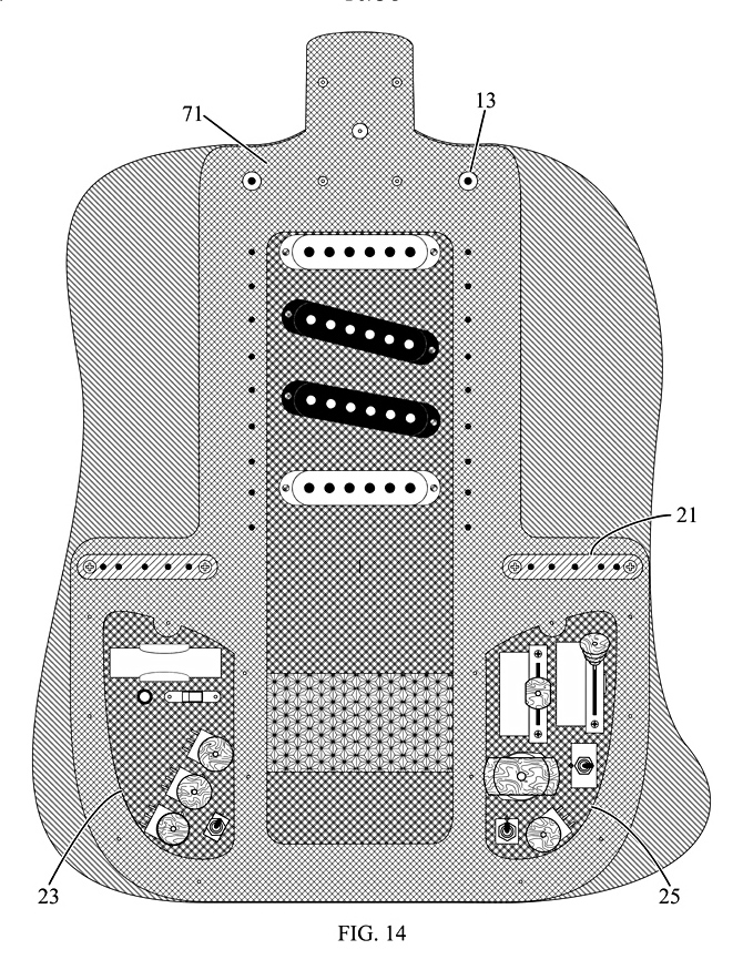
FIG. 14 show the core profile (71), with the soundboard mounting posts (13) mounted in it, the screw plate (21) mounted on it, and the left (23) and right (25) electronics cavities cut through it.
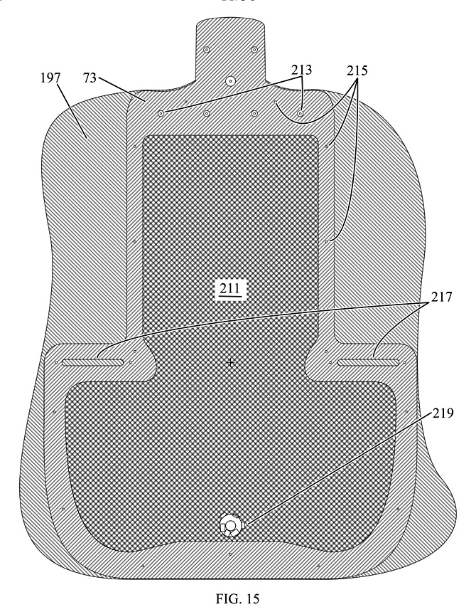
FIG. 15 shows the lower profile (73), with screw pass holes (217)
for the bridge line soundboard mounting and adjusting screws, the
output jack (219) mounted on the bottom cover (197) electrically
connected to the shield (211), pilot holes (215) for the screws
mounting the bottom cover to it, and optional pass holes (213) for
the soundboard mounting screws at the neck.
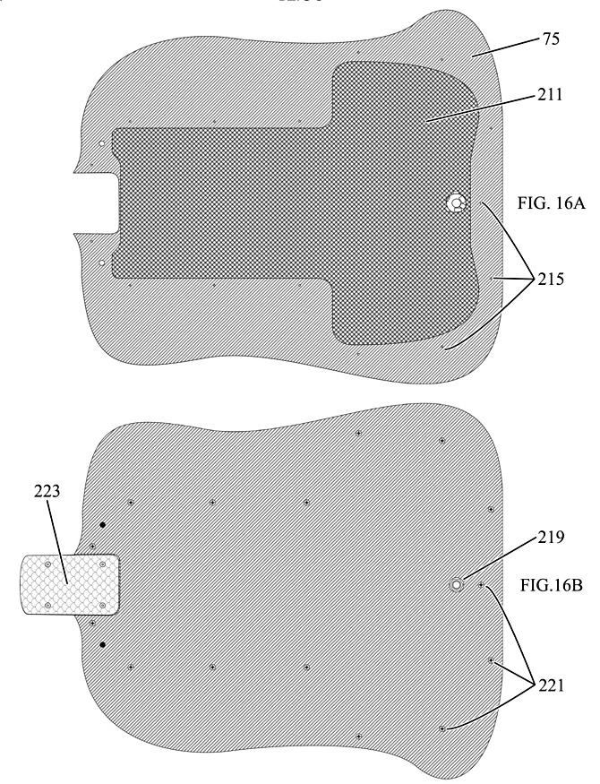
FIG. 16 shows the top (16A) and bottom (16B) of the bottom cover (75) with the full extent of the shield (211), the mounting screws (221) corresponding to pilot holes (215), the musician's end of the output jack (219, 16B), and the screw plate (223) for the neck screws.
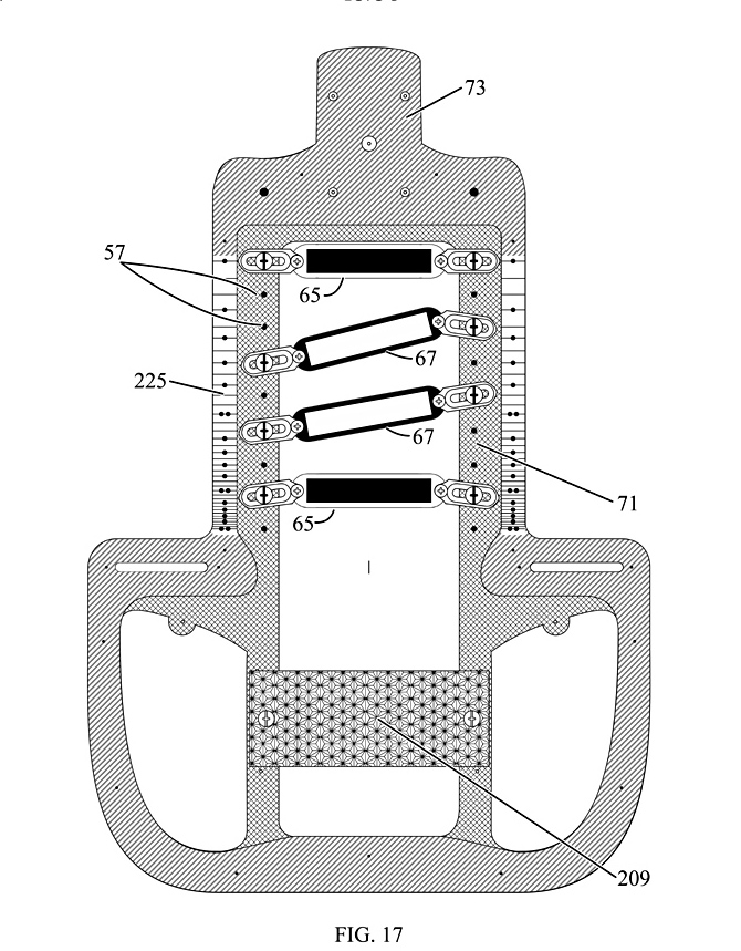
FIG. 17 shows the bottoms of the lower profile (73) and core
profile (71) with the pickups (65, 67) mounted from the bottom, using
the same threaded holes (57) as the top mounting system. Here the
fret scales (225) are inscribed on the bottom of the lower profile.
It also shows the electronics circuit board (209) fixed to the bottom
of the core profile. The lower profile is just wide enough at the
margins to provide screw holes for securing the bottom cover, while
passing or providing access to the pickps and electronics.
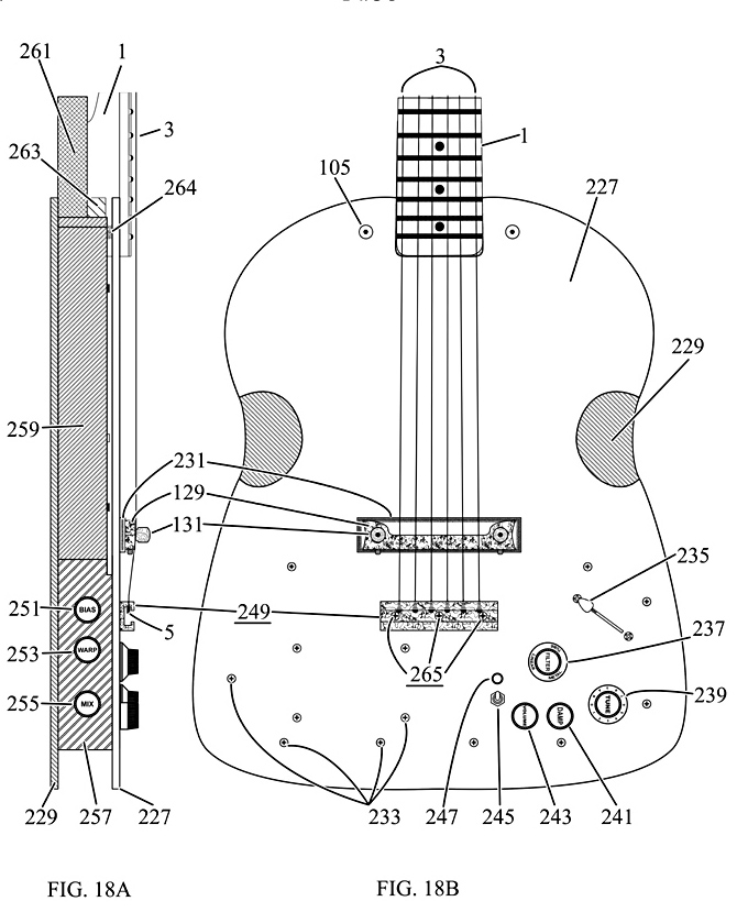
FIG. 18 shows an alternative body and soundboard design conforming
the this patent. The neck (1), strings (3), soundboard mounting screw
at the neck (105), bridge (129), and bridge hold-down knobs/screws
(131) are much as before. The neck screw plate (223, FIG. 19) got
left off unintentionally. The alternative soundboard (227) and bottom
cover (229) are cut to a different pattern, and the bridge base (231)
is more compact. In this case, the height of the strings on the
bridge (129) is fixed by the thickness of the bridge, bridge base,
and soundboard. The new tailpiece (249) is closer to the bridge to
allow more space for controls and indicators (235, 237, 239, 241,
243, 245, 247). Screws (265) pass through the soundboard, mounting
the tailpiece to the core profile (261) and tailpiece base (275, FIG.
19). Various screws (233) mount the soundboard to the control box
(257) and the controls to the soundboard. The bottom cover (229)
attaches to the sides (259) and the control box. The flat sides of
the control box allow controls (251, 253, 255) to be mounted on the
left side, out of the way of playing and picking.
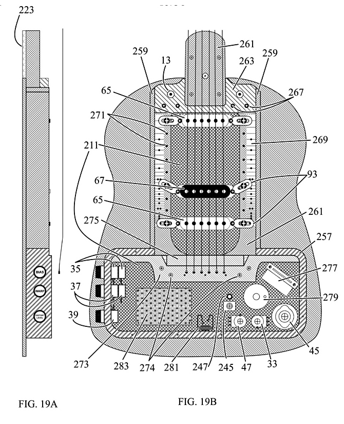
FIG. 19 shows the soundboard removed, but the strings left in
place to show their relationship to the pickups (65, 67), which are
mounted using flat plates (93) to holes (271) in the core profile.
Here the fret scale (269) is inscribed on the upper side of the core
profile (261). The neck socket (263, FIGS. 18 & 19), the
tailpiece base (273), screwed (274) to the core, replace the upper
profile. The tailpiece base has a bevel cut (275) at the neck side
edge of the tailpiece to facilitate transfer of vibrations from the
bridge to the soundboard. The control box slides into a slot between
the sides and tailpiece base and is attached to the tailpiece base.
Also shown are electronic components (33, 35, 37, 39, 45, 245, 247,
277, 279, 281, 283) within the control box.
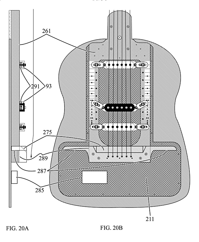
FIG. 20 shows the full extent of the electrostatic shield on the bottom cover (211), how the core (261) extends under the tailpiece base (275) in a shallow dado cut (289), the wings on the tailpiece base (289) to which the control box attaches, more detail of the bevel cut (275), the battery box (285) attached to the bottom cover, and the pickup mounts (93) with thicker vibration-absorbing layers (291).
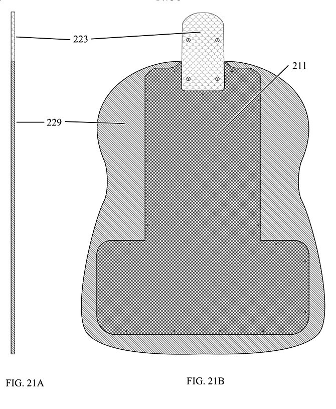
FIG. 21 shows the bottom cover and the placement of the neck screw
plate (223).
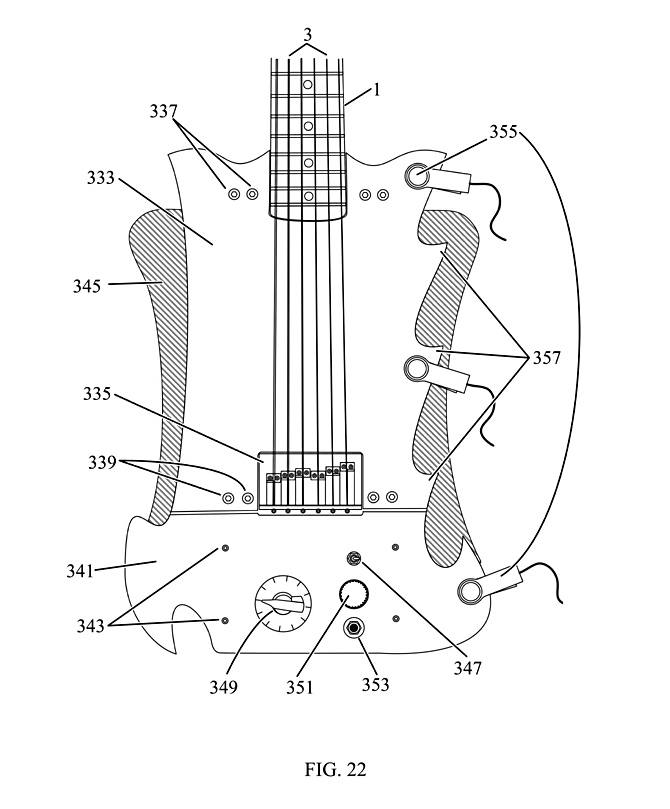
FIG. 22 shows the second prototype, with a core (not shown) made
of red oak, a two-piece soundboard (333, 341) and back (345) made of
masonite, a metal top-loading bridge (335), and two pickps of
opposite magnetic polarity (not shown) as in FIG. 22C. The upper
soundboard (333) is mounted by four machine screws (337) on a neck
socket (not shown) rising above the oak core, and four screws (339)
on a bridge base (not shown) rising above the oak core. The lower
soundboard (341) is bolted (343) to a set of rails (not shown) on the
body, with controls (347,349, 351) and an output jack (353) mounted
on it. The soundboard had much more acoustic output that a standard
solid-body electric guitar, but much less than an acoustic guitar.
But still enough so that a contact microphone (355) can easily pick
up signals on the barbs (357) on the soundboard. Each barb produces a
different timbre. Thus vibration sensors incorporated into the
soundboard at various places can also produce useful output.
FIGS. 23-31 Describe Improvements to the Pickup Switching System
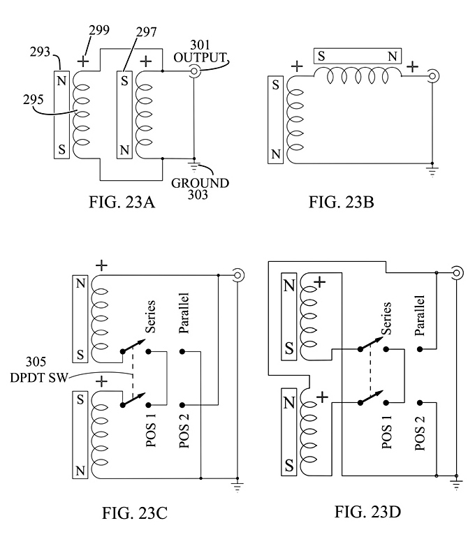
FIG. 23A shows the basic parallel coil humbucking circuit, for
either two single-coil pickups, or a dual-coil humbucker. FIG. 23B
shows a series connected circuit. Humbucking refers to the ability of
the circuit to cancel out external varying magnetic fields that do
not arise from the interaction of the strings and the pickup. This
drawing presents a single-coil pickup in the simplest possible terms:
a magnet (293), a coil of wire (295, usually around or above it), and
a lead designated "+" (299) which has the same phase of
signal as all the other pickups in the circuit with "+"
leads. Standard symbols for the signal output (301) and ground (303)
are shown.
Say there are two pickups, one with its north
pole (293) next to the strings (or upwards), and the other with the
south pole (297) next to the strings. If the coils are wound in the
same direction, say CCW in the top view (or left-handed), and are
near each other with respect to the vibrations of the string, then
the vibrations will produce signals of opposite phase in the same
respective leads on each coil, because the magnetic poles are
reversed. The leads of one coil must be reversed to keep from
canceling out the string signal. But this will cause an external
signal, like 60 cycle machinery and light signals, which has nothing
to do with the pole oriention, to cancel. Thus "humbucking".
It is convenient not to show crossed leads for one coil, but to
simply assign the in-phase lead to the top and label it "+".
In order for this to work, both coils have to have the
same number of effective turns, which can be influenced by an
artificial and/or intended concentration of the external field in the
instrument. In general, most replacement pickups will have to be
wound to match the pickup in the set with the highest signal output
of external fields. Also the series circuit tends to have a stronger
signal with less high frequencies (warmer), and the parallel circuit
tends to have a weaker signal with a peak in higher frequencies
(brighter).
FIG. 23C shows a switched circuit, using a
double-pole double-throw (DPDT) switch (305) to produce series and
parallel outputs, like 23A and 23B. Rather than having switch arrows
that rotate to a number of positions (throws), this diagram uses
slightly non-standard symbolism, which puts the poles on the right
and the switch positions for "throws" successively to the
left. It makes the circuits a lot easier to draw and understand. Note
that the + wire of the north-up pickup is connected permanently to
the output and the other wire of the south-up pickup is connected
permanently to the ground, which makes humbucking circuits easier to
draw, with a minimum number of switch poles. So switch position 1
(POS 1) is made series merely by connecting the two switch terminals
together, and position 2 (POS 2) is made parallel by the N-up coil
switch terminal to the ground and the S-up terminal to the output.
FIG. 23D shows how two N-up single coils are connected in
series and parallel circuits. Here, the N-up pickup from 23C is moved
down and replaced with another N-up pickup with the "+"
wire connected to ground. Because the pickups are both N-up, both the
external and string signals tend to cancel each other. But the string
signals will still be stronger because of the presence of higher
harmonics of the fundamental frequencies of vibrations, which this
circuit tends to emphasize.
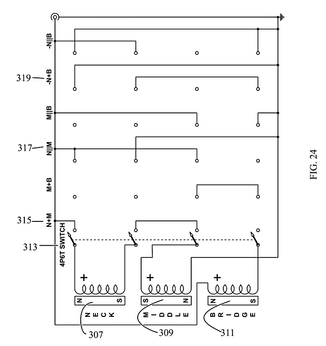
FIG. 24 shows how three pickups can be connected into six
humbucking pairs with a 4P6T switch (313), using the previous
switching symbolism. The neck position pickup (307) and bridge bridge
pickup (311) are N-up, with the middle pickup (309) S-up. The number
of possible pickup combinations of one type, series or parallel, of
three pickups taken combined in pairs is (3*2)/(2*1) or 3, making 6
total for both series and parallel. This includes the opposing signal
(out-of-phase) pairings of the two N-up pickups. Here the symbolism
at the switch positions for the connections uses "+" for
series (315), ".parallel." for parallel (317), and "-"
for an opposing signal (319). This makes the circuit diagram easy to
read and understand at a glance. Note that for a commercially
available 5-way guitar "superswitch", which is 4P5T, one of
the combinations must be left off (likely -N.parallel.B).

FIG. 25 shows a 6P6T switching circuit for two N-up pickups at the neck (307) and bridge (311), with two S-up pickups in between in the Middle 1 (321) and Middle 2 (323) positions. Here four pickups taken two at a time in series produces (4*3)/(2*1) different pairs, or 6.
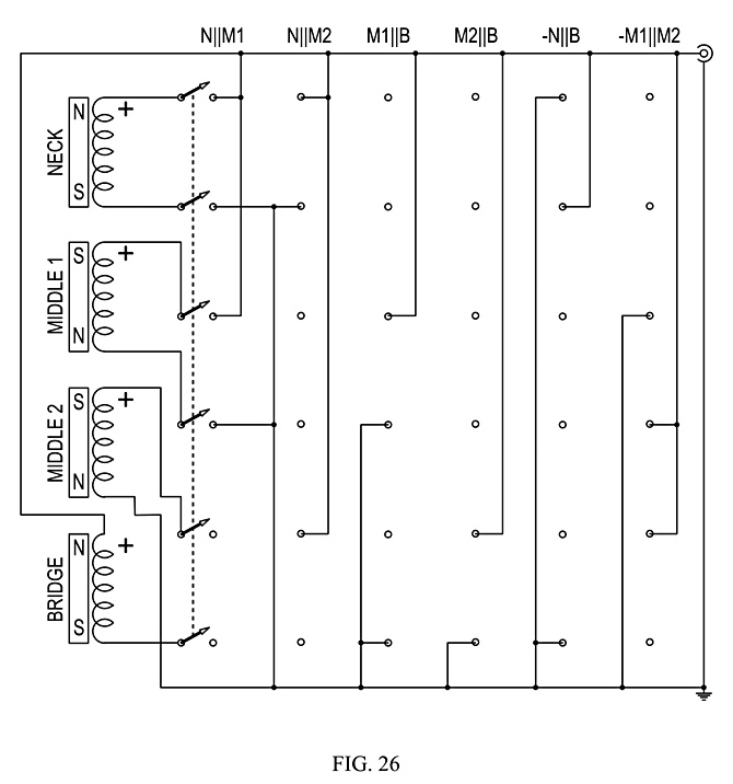
FIG. 26 shows the corresponding 6P6T switching circuit for
parallel connections. Both figures together produce 12 combinations
of humbucking pairs. The least number of switch poles necessary for
the circuit to work depends on the number of magnetic poles up. If
all K pickups have the same polarity of poles up, then a switch with
switch with 2*K-1 poles is needed, and only one pickup can have a
permanently connected wire, with the other served by a single pole.
If at least one pickup has a different polarity, then a switch with
2*K.times.2 poles is needed, and a single pickup of each polarity up
can have permanently connected wires and be served by single switch
poles.
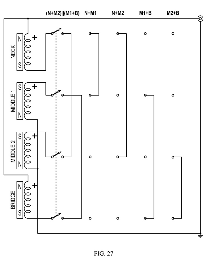 FIG. 27 shows a different set of series circuits with a 4P5T 5-way
"superswitch" used on the fourth prototype to connect
together series humbucking pairs of single-coil pickups. Note that
this circuit uses the same permanent connections with N-up and S-up
as 22C. Here the first switch position connects all pickups together
as two series circuits in parallel, which the remaining four
positions are the remaining series combinations that do not have any
out-of-phase signals. The first position tends to give a signal that
sounds like an acoustic guitar. The rest of the positions become
brighter in tone and timbre from left to right.
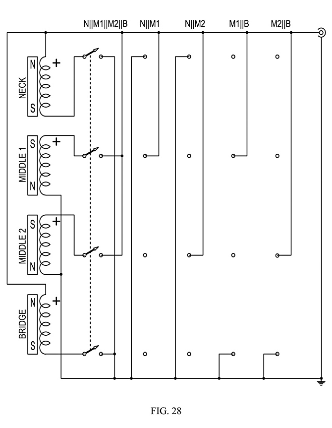
FIG. 28 shows the same kind of circuit used in the fourth
prototype for parallel humbucking pairs, with all four connected in
parallel in the first position. The first position also emulates an
acoustic guitar, but slightly brighter. Again, the timbres get
brighter from left to right. Both FIGS. 27 and 28 show connections
for humbucking quad pickups. The number of unique possible
combinations for just four pickups, connnecting serial-parallel
humbucking pairs in serial or parallel to serial-parallel humbucking
pairs are less straightforward to calculate. Note that for four
pickups connected together in serial there is only one possible
combination of four pickups, as there is for four pickups connected
together in parallel. Otherwise, there appear to be four sets of
three combinations for the pairs, for a total of 14 unique
combinations. The predicted outputs for these combinations are about
1, 2, 3 and 4 times the output for a parallel-connected humbucking
pair, not counting the combinations with signals that are out of
phase.
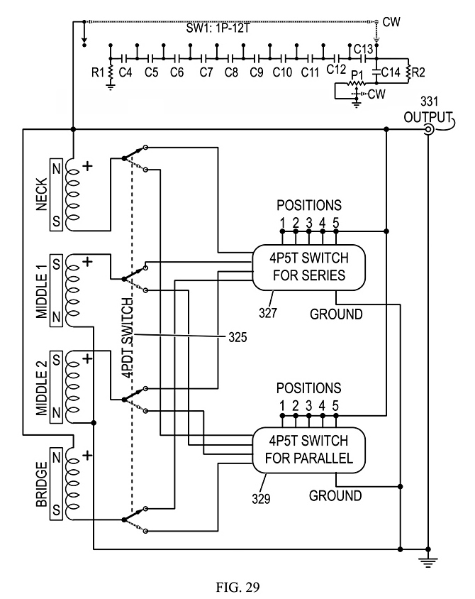
FIG. 29 shows how the fourth prototype combined FIGS. 27 & 28
by using a 4PDT switch to switch the pickups from the series 5-way
switch (FIG. 27) to the paralled 5-way switch (FIG. 28). Thus
producing 10 humbucking outputs compared to the 2 generated by a
single standard 5-way switch on most Stratocasters (.TM.Fender) and
their imitators.
This switching system can be expanded to
any number of single-coil pickups, or four-lead humbucking dual coil
pickups. Generally, unless one wants most of the humbucking outputs
to be combinations of out-of-phase signals, the number of S-up single
coil pickups should number no more that one more or less than the
number of N-up pickups. Five pickups, for example have (5*4)/(2*1),
or 10 series humbucking combinations, and an equal number of parallel
humbucking combinations, for a total of 20. In the case of 3 N-up
pickups and 2 S-up pickups, the switch would need two poles each for
two of the N-up pickups (4) and one of the S-up pickups (2), plus one
each for the remaining pickups (2), for a total of 8 poles and 20
throws or positions (8P20T, or two 8P10T plus an 8PDT) to get 20
series-parallel combinations of signals.
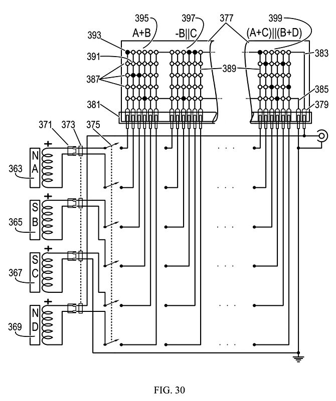
FIG. 30 shows a more flexible embodiment than making all the
connections in FIGS. 23-27 directly on the switches and their
terminals. N-up pickups A (363) and D (369) and S-up pickups B (365)
and C (367) each have wires ending in female connectors (371), which
plug into male pin or header connectors (375). These connectors can
be either keyed (polarized) or unkeyed. Unkeyed connectors can be
reversed in the event of a pickup wiring error. The connectors allow
other arrangements of the pickups between the neck and bridge (or
tailpiece), such as N-N-S-S or N-S-N-S, or vice versa, to accommodate
other musical theories and settings.
The male pins (375)
are connected to a 6P6T switch (375), as in FIGS. 24 & 25. The
six wires for each switch position are connected to a female circuit
board connector (381), into which a circuit board (377) plugs with
board-edge finger contacts (379). The board has vertical wires (389)
on one side for the switch terminals, and horizontal wires on the
other side, consisting of a common output wire (383), a common ground
wire (385) and several interconnect wires (387) that are separate for
each switch position.
Open circles (391) designate cross
points where the horizontal and vertical wires do not connect. Filled
circles (393) represent cross points with connections between the
horizontal and vertical wires. If the open circles represent holes
through the board, this can be as simple as a jumper wire soldered
from one side to the other. Here, the connections for A+C (395),
-B.parallel.C (397) and (A+C).parallel.(B+D) (399) show at three of
the switch positions. Otherwise, the same thing can be done with
commonly available analog and/or digital semiconductor crosspoint
arrays, and a microcomputer driver. In this case, only two of the
interconnect wires (387) are necessary, requiring interconnections
between 6+4 or 10 wires. So theoretically, 10.times.10 or 16.times.16
integrated circuit crosspoint switch matrix could accomplish the same
thing as the 6P6T or 6P12T switch (375) and the matrix board (377)
combined, to produce all 12 serial and parallel humbucking
combinations. Thus the embodiments are not limited to the physical
features of FIG. 30.
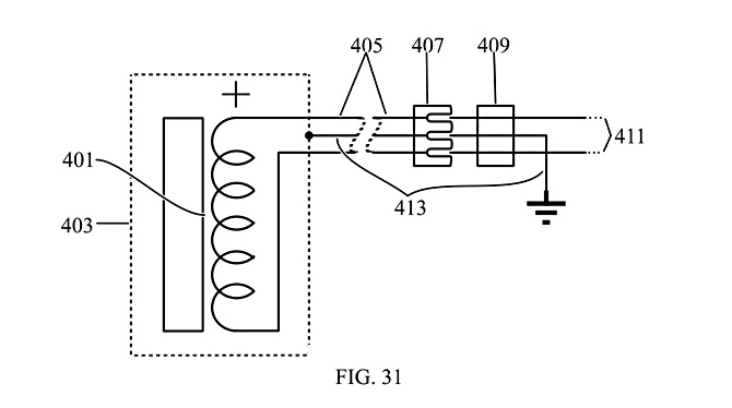
FIG. 31 shows an improved pickup connection embodiment, with
shielding. The pickup (401) is enclosed by and electrostatic shield
(403), from which a 3-wire cable (405) emerges with the two signal
wires (411) and a ground wire (413) connected to the shield. It
terminates in the three-pin female connector (407) which connects to
the 3-pin male connector (409), with the ground wire in the center.
The ground wire is grounded on the other side of the male connector.
The 3-conductor cable can be either ribbon cable, as implied here, or
2-wire twisted and shielded cable, or even 5-conductor ribbon cable
with ground wires bracketing the signal wires, as are some computer
cables, but with only center wire connected to the pickup shield.
This would provide better rejection of high-frequency noise pickup
from things like fluorescent lights. With either a 3-wire
high-gnd-low or S-wire gnd-high-gnd-low-gnd system, the connector
will be reversible if not keyed or otherwise polarized.
FIGS. 32-50 Describe the on-Board Signal and Distortion Control
Circuits
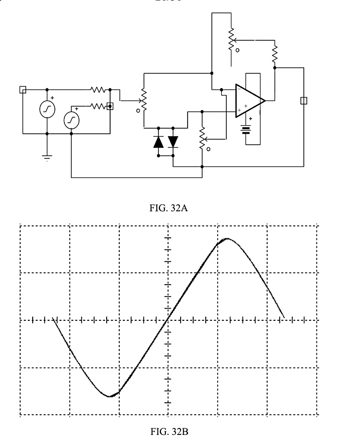
FIGS. 32A-B show respectively a circuit developed and its transfer function, simulated in TINA-TI Ver. 7 (.TM.DesignSoft, Inc.) by this inventor on Dec. 24, 2007.
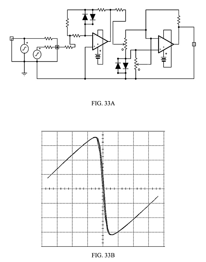
FIGS. 33A-B and 34A-B show similar circuits and their transfer functions, also simulated in TINA-TI by this inventor on Dec. 24, 2007.
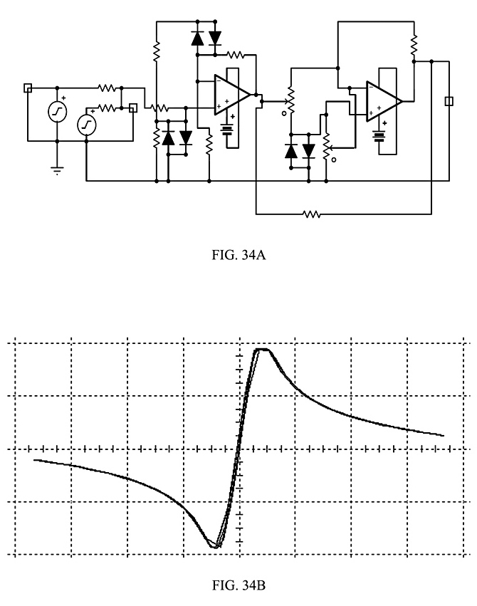
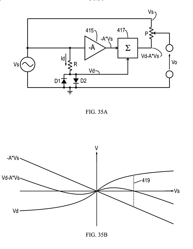
FIG. 35A shows the block function of basic circuit that produces such curves, with voltages calculated versus the input voltage, Vs, in FIG. 35B. Variations in components and their values in the other circuits produce the differences in curve shape.
The basic circuit in FIG. 35A comprises just a few simple ideal component functions. Given a signal source, Vs, the resistor, R, and diode pair, D1-D2, form a non-linear voltage divider with a partially logarithmic current, Id, and a partially logarithmic output, Vd, as shown in FIG. 35B. The equation for a single ideal diode is:
Math 4.
![]()
The equation for a pair of diodes in parallel, connected
anode to cathode, is:
Math 5.
![]()
The non-linear voltage divider in FIG. 35A cannot easily be
solved for Vd directly, as the function is related to x
= y*ey.
Instead, here it is plotted in a spread sheet and solved graphically
using the equation:
Math 6. Vs(Vd)=Vd+Id*R using [Math 5.]
It produces a
plotted inverse function, Vd(Vs), in FIG. 35B that looks like
something a stretched-out italic-f.
The circuit in
FIG. 35A has an ideal amplifier (415) with gain -A, where 0<-A<-1,
produces the signal, -A*Vs. An ideal summer (417) adds the signals to
get Vd-A*Vs. Very near Vs=0, the function Vd(Vs) has a linear slope,
with Vd=Vs. But for increasingly higher values of Vs, Vd increases
logarithmically, which is much slower than A*Vs. So the italic-f
curve can be warped toward zero at the ends, and made to recross the
horizontal axis. As shown in FIG. 35B, this signal has a lazy-S,
valley-peak function versus Vs, with three zeros. Note the third zero
at the dotted line (419), where Vd=A*Vs. The outer zeros are modified
by the gain, -A, by the resistor, R, and the characteristics of the
diodes, D1 & D2. If a larger signal, Vs, is used, then the zeros
fall closer to the vertical axis with respect to its peak-to-peak
amplitude.
Adding the ideal potentiometer, P, produces an
output, Vo, which can vary continuously from Vs to Vd-A*Vs with its
setting. Thus the transfer function of the entire circuit, Vo(Vs),
can vary from linear, Vo equal to Vs, then to Vd, which simulates
1960s tube amplifier distortion, then all the way to Vd-A*Vs. Which
tends to emphasize third-order harmonics of Vs, for a more metallic
sound, especially if components are used which are more non-linear,
or more non-linearities are added, to produce sharper curves, as
shown in FIGS. 32B, 33B and 34B.
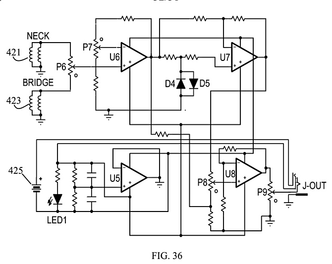
FIG. 36 shows the circuit installed in a Fender Squier.TM. guitar
on or before Jan. 10, 2008, using the basic circuit in FIG. 35. The
routing of additional and expanded cavities in its body provided the
space for another pickup at the neck, a plastic electronic breadboard
and a 9-volt battery box. A new clear acrylic pickguard allowed
mounting of the new pickup and additional controls. Phono jack J-Out
contains a switch that complete the connection of the battery to the
circuit when the phone plug is inserted, whereupon LED1 lights.
Op-amp U5 is a ground-driver, which allows +V and -V supply voltages
from a single battery (425).
Potentiometer P6 combines
the signals from a double-coil humbucking pickup at the NECK (421)
and one at the BRIGDE (423), changing the signal continuously between
them. The warmest position, with the lowest content of higher
harmonics, turns out to be the middle, where the two pickups are
equally combined. Op-amp U6 is a preamp, with the positive gain
controlled by P7. Raising the gain has the same effect as changing
the gain -A in FIG. 35B closer to zero, which drives the outer zeros
of Vd-A*Vs in FIG. 35B closer to the vertical axis, with respect to
the amplitude of Vs. Diodes D4 & D5 provide the necessary
logarithmic non-linearity. Op-amp U7 functions as the summer in 35B,
further modifying the gain of the U6 circuit and changing it to
negative. Potentiometer P8 serves the function of P in FIG. 35B,
mixing the linear and non-linear signals equivalent to Vs and
Vd-A*Vs. Op-amp U8 adds a final buffering and gain stage, with P9 as
a volume control connected to the output jack.
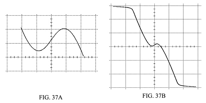
FIG. 37A shows the transfer function of the circuit in FIG. 36,
simulated in TINA-TI, for a certain input signal, with P7 set at 1%,
near the zero on the potentiometer symbol. It demonstrates a nearly
symmetrical peak-valley, lazy-S curve, on a scale of 50 mV per
division. Note that it has an uncorrected voltage offset from zero.
FIG. 37B shows the transfer function for P7 set at 99%, on a scale of
500 mV per division, ten times higher. Here, the output signal has
reached the limits of the battery power supply and is clipped at the
upper and lower ends. Unless this kind of behavior is desirable,
component selection and testing should be conducted for any change in
or range of conditions, such as pickup model and mounting.
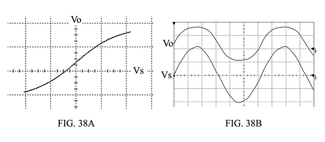
FIG. 38A shows the simulated transfer curve of the circuit in FIG. 36 with P7 set to low gain, and P8 set to about 30% nonlinear signal in the output. Note that it approximates 1960s tube amplifier distortion. For reference, FIG. 38B shows the amplified input signal, Vs, at the output of U6, and the output signal, Vo, of U8, both simulated.
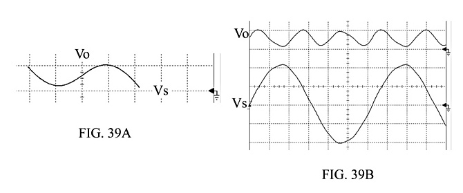
FIG. 39A shows the simulated transfer curve of the same circuit
with P8 set at about 99% nonlinear signal in the output. FIG. 39B
shows the amplified input signal, Vs, and the resulting output
signal, Vo. Note that the output signal is virtually the third
harmonic of the input signal and has a much lower amplitude.
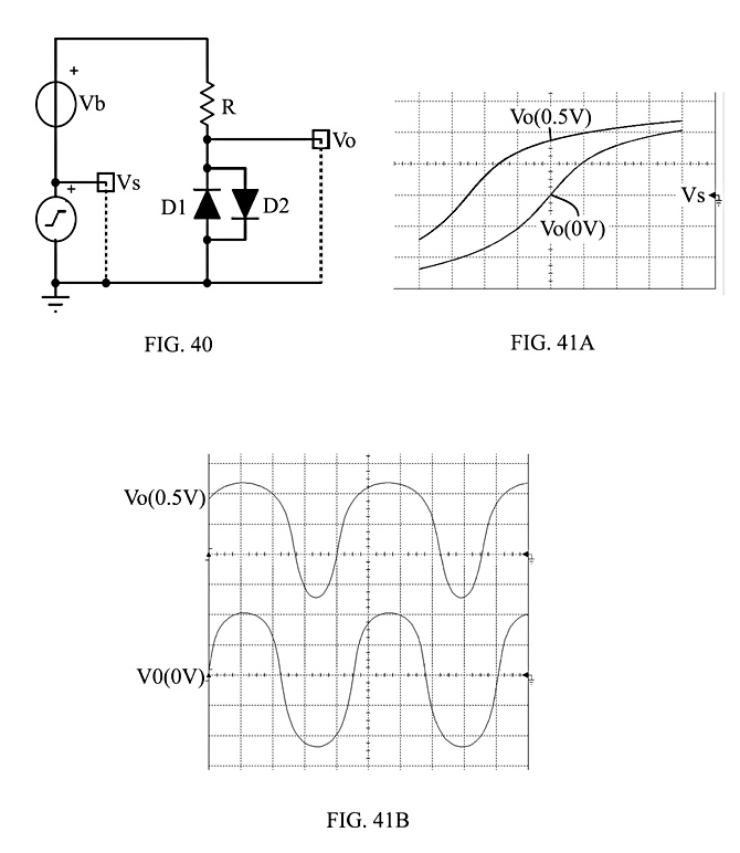
FIG. 40 shows a simple circuit to simulate 1960s tube amplifier
distortion, using the non-linear voltage divider comprised of R, D1
and D2, with an output Vo. An added ideal voltage source, Vb,
provides a bias voltage that shifts the operating point of the
voltage divider from the symmetrical center of its transfer curve to
the upper shoulder, as shown in FIG. 41A for Vb settings of 0 V and
0.5V. FIG. 41B shows the resulting signals, Vo(0V) and Vo(0.5V).
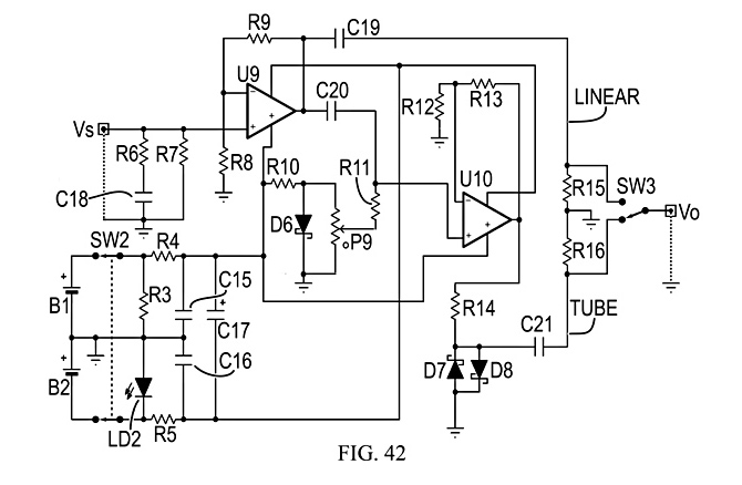
FIG. 42 shows the version of this circuit installed in the fourth
prototype. It runs on two AA cells (B1, B2), and has enough output to
drive a standard guitar amplifier, even though the pickups (FIG. 12,
65, 67) sit below the soundboard (FIG. 2, 69). When turned on, the
DPDT switch, SW2, cause the power indicator (R3, LD2) to light, and
powers the circuit through a noise filter (R4, R5, C15, C16, C17).
The signal from the switched pickups and tuning capacitor (FIG. 29,
331) is applied at the signal input, Vs. A low-pass filter circuit
(R6, R7, C18) impedes high frequency noise above 10 KHz. A preamp
(U9, R8, R9) boosts the signal by a factor of about ten, and feeds
the linear signal (LINEAR) to other parts through capacitors (C19,
C20). The variable bias circuit (R10, D6, P9) performs the function
of Vb in FIG. 40, via the signal blocking resistor (R11) and
amplifier (U10, R12, R13). This drives the non-linear voltage divider
(R14, D7, D8), which produces a signal like tube amplifier distortion
(TUBE). A switch with ground-bleeder resistors (SW3, R15, R16)
provides the instrument player with a choice of LINEAR or TUBE
signals.
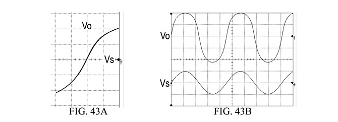
FIG. 43A shows the TINA-TI-simulated transfer curve of Vo(Vs) for P9 set near ground for low bias voltage. FIG. 43B shows the resulting simulated signals for Vs and Vo with respect to time, not at the same vertical scales. Note the result for a transfer curve with a nearly symmetrical italic-f character.
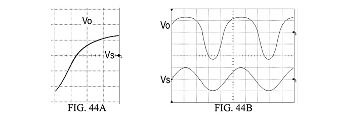
FIG. 44A shows the simulated transfer function of Vo(Vs) for P9
set to high bias, near the full voltage across D6. Note that the
curve is an extension of that in FIG. 43A, with the operating point
of the signal up on the positive shoulder. FIG. 44B shows the
resulting simulated signals for Vs and Vo. Note the highly
non-linear, non-symmetrical result. In practice, the transfer curve
is a bit more extreme, and produces a kind of string-popping effect,
with a burst of tone which quickly tapers off in amplitude to a much
lower signal, an effect that had not been heard before by the
professional musicians who initially reviewed it. Otherwise, the
lower bias settings sounded to one musician like a 1960s tube
amplifier.

FIG. 45 shows the combined functions of FIG. 35 and FIG. 40. The linear signal, Vs, is added to a bias signal, Vb, and applied to the non-linear voltage divider (R17, D9, D10) to generate the non-linear signal, Vd. Potentiometer P10 provides a fraction of the linear signal, A*Vs, which is applied to the negative input of the summing amplifier (U11, R18, R19). There are two resistors each of R18 and R19, because they are the same values, respectively. They produce a summing amplifier gain of G>1. The signal Vd is applied through the DC voltage blocking capacitor (C22), which removes the bias voltage, Vb, to the positive input of the summing amplifier. Thus, if Vs and Vd are measured in volts peak-to-peak, the distortion signal, Vdist, has an AC peak-to-peak value of:
Math 7. Vdist=G*(Vd-A*Vs), where G>1, determined by R18 and
R19, and 0<A<1.
The output potentiometer, P11,
provides an output voltage, Vo, which is a continuous mixture of
signals from Vs to Vdist.

FIG. 46A shows the Vo(Vs) transfer curve when P11 is set to 0%. FIG. 46B shows the resulting signal, Vo(t), displayed here as a sine wave, and equal to Vs. For a given input signal, Vs, varying Vb, P10, and P11, with G as a parameter, a wide variety of timbres can be obtained from the fundamental frequency of Vs through the second harmonic to the third harmonic. For P11 set to 100%, Vo is equal to Vdist. For setting of P11 in between, expressed as the fraction, Vo has an peak-to-peak value of:
Math 8 . Vo=(1-B)*Vs+B*G*(Vd-A*Vs), where B=P11%-setting/100, or
Vo=(1-B*(1+G*A))*Vs+B*G*Vd
Thus Vo is only a function of
Vd, if:
Math 9 . B=1/(1+G*A)==>Vo=B*G*Vd
There are two
special cases for B=1, or Vo=Vdist, one for Vb=0 and one for Vb=some
Vbmax, where Vb is adjustable between 0 and Vbmax.

FIG. 47A shows the one for Vb=0, where A is set so that the transfer curve of Vo(Vs) folds with the two most positive values of Vo are closest to each other, while the two most negative values of Vo are closest to each other. This produces the output shown in FIG. 47B, Vo(t), which has the highest possible component of the third harmonic of Vs. In this example with the components and particular amplitude of Vs chosen, this happens to occur for A=0.38.

FIGS. 48A and B show the other case, where Vb=Vbmax, and A is set
so that the two most negative values of Vo(Vs) are closest to each
other, so that Vo(t) has the highest possible content of the second
harmonic of Vs. In this particular example, this happens to occur for
A=0.25.
Notice that the peak-to-peak amplitudes in FIGS.
46B-48B are not equal. Because Vdist is the difference between the
non-linear and linear signals, it is generally smaller in
peak-to-peak amplitude than the linear signal, Vs. G is set so that
the geometric mean of the peak-to-peak amplitudes of Vo(t,Vb=0) and
Vo(t, Vb=Vbmax) is roughly equal to the peak-to-peak amplitude of the
chosen typical Vs. This makes the log difference between Vs and the
two extremes of Vdist(Vb) about the same. In this particular example,
it was about 15.2 and thus may be on the order of 10 to 20. But
without further compensation, the peak-to-peak amplitude of Vo will
still change with the settings of Vs, Vb, P10 and P11.
Note
also that the conditions in FIGS. 47-48 can only occur for one
amplitude of the input signal, Vs. Absent any other circuit to
compress or equalize the amplitudes of signals from electrified
stringed instrument from, a plucked or struck string generates a
dynamic signal, decaying in amplitude with time. If Vs starts out
larger than that needed for the Figures, the fundamental harmonic
component of Vo will start out inverted compared to Vs, and decrease
as the signal passes through the conditions of FIGS. 47-48. It will
gradually reassert itself as Vs becomes smaller than that condition.
An improved embodiment covered by this patent shall
include an automatic gain or compensation control, whereby A in FIG.
35A is inversely proportional to a running average of the
peak-to-peak magnitude of the string vibration signal, Vs. A running
average of the magnitude Vs over a limited time or number of cycles
will keep the zeros (FIG. 35B, 419) in Vd-A*Vs relatively constant in
the output signal, Vo, while allowing the it to retain the dynamic
nature of Vs. This kind of circuit has been applied in radios for
decades; the trick here is knowing that it must be applied to the
value of A.
The electronic timbre imposed by this circuit
will be highly dependent upon the setup of the pickups, guitar,
circuit components and settings, and the style of play, soft or hard
and aggressive. Nevertheless, this simple circuit provides huge
continuous changes for the player in the dominant timbre of the
stringed instrument's electronic output, from the fundamental to the
third harmonic.
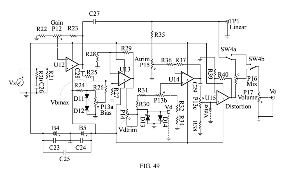
FIG. 49 shows an embodiment of the circuit in FIG. 45 which has
been simulated in TINA-TI. It provides the functions of that circuit,
plus a variable-gain pre-amp and amplitude compensation so that the
output conditions in FIGS. 46B-48B have nearly equal peak-to-peak
amplitudes. For clarity, the terms Vs, Vd, Vdist and Vo have been
retained. The circuit is powered by two batteries (B4, B5), filtered
by three capacitors (C23, C24, C25). The input has a low-pass noise
filter (R20, R21, C26), connected to a variable-gain pre-amp (U12,
R22, R23, P12(Gain)), feeding out through DC blocking capacitors
(C27, C28) to the rest of the circuit.
In lieu of a
semiconductor precision voltage reference in TINA-TI, the maximum
bias voltage, Vbmax, in FIG. 45, Vb, is derived here from a pair of
diodes in series (D11, D12), driven from the positive supply (B5)
through a resistor (R24). It could be replaced by such devices as the
LM285 and LM234.
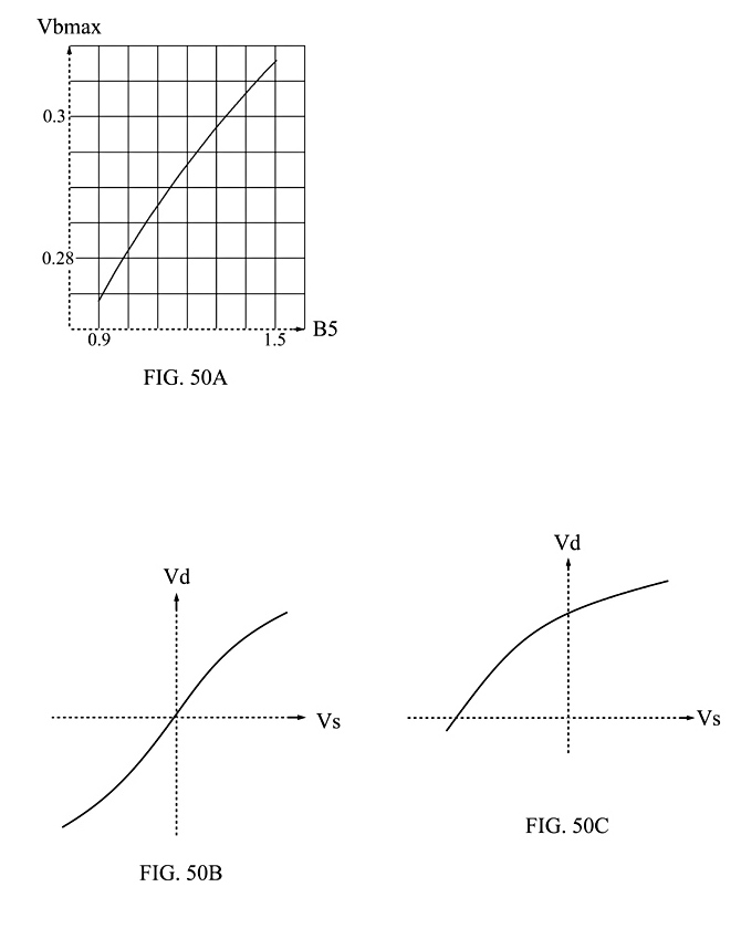
FIG. 50A shows an estimated typical response of Vbmax to changes
in the voltage of battery B5, on the order of 0.31V to 0.27V (or
-13%) in Vbmax for changes of 1.5V to 0.9V (or -40%) in B5, as B5
discharges. Assuming that B4 and B5 have capacities of at least 1500
mA-Hr, the batteries should last on the order of 400 hours of
operation. So the effect on the character of the output signal should
be gradual over that time. An improved embodiment covered by this
patent shall include a precision voltage reference of value on the
order of 0.3 to 0.6 volts.
A variable portion of Vbmax,
taken from the first gang (P13a(Bias)) of a 3-gang potentiometer
(P13a-c), is summed with the amplified input signal, Vs, through an
amplifier with a gain between 1 and 2 (U13, R25, R26-R29). This is
applied to a non-linear voltage divider (P14, D13, D14), which
generates the non-linear signal, Vd(Vs). FIG. 50B shows the
approximate shape of this signal for Vb=0. FIG. 50C shows the
approximate shape and offset of Vd(Vs) for Vb=Vbmax.
A
portion of the linear signal, Vs, taken from a voltage divider (R35,
P15(Atrim)) is subtracted from it in a summing amplifier (U14, P13b,
R30-R34, R36, R37), to which a portion of Vd is added. The summing
amplifier has a gain between 10 and 20. The result is applied a DC
blocking capacitor (C29) to a voltage divider (P13c, R38) to generate
the distortion signal, Vdist. The second gang (P13b) of P13 turns in
lock step with the others. The values of all the resistances (P15,
R30-37) associated with D13, D14 and U14 are chosen so that for a
given amplitude of Vs and gain of the pre-amp via P12, and a single
setting of P15(Atrim), the signals for Vdist, as a function of Vb
equal to zero and Vbmax, are the same character as FIGS. 47 & 48.
The value of resistor R38 then ensures that the output of
the third gang (P13c) of P13 produces signals like FIGS. 47 & 48
with the same amplitude. The gain of the amplifier formed on U15
(U15, R39, R40) ensures that those amplitudes are approximately the
same as the signal of Vs after amplification by the pre-amp (U12,
P12, R22, R23), called Linear at Test Point 1 (TP1). The output of
U15 is called Distortion. The Linear and Distortion signals are
applied to either end of the Mix potentiometer, P16, allowing a
continuous and linear mixture of those signals. The optional
double-pole, double-throw switch, SW4, provides the Volume pot (P17),
and output, Vo, with choice of Linear or Mixed signals, in case the
non-linear parts of the circuit become malfunctioning or maladjusted.
As a consequence of all these manipulations in amplitude,
for the particular input signal, Vs, that produces outputs at Vo with
the character of FIGS. 46-48, the amplitude of Vo does not markedly
change with changes in the settings of P13 and P16. This may save the
stringed instrument player the pain of making many more adjustments
for every change in the Bias and Mix controls. As a consequence,
P15(Vdtrim) and P16(Atrim) need not have external control knobs, and
can be set for a particular guitar, with infrequent adjustments
needed only for the player's preferred style of play, or changes in
pickup model or spatial adjustments in the guitar.
* * * * *