
Limited license for a book sale
This Chapter explains a type guitar pickup circuit disclosed in U.S. Patent 10,380,986 (Baker, 2019) and further developed in U.S. Patent 10,810,987 (Baker, 2020) and other patents. Can you make one and try it out for yourself? When a patent has been granted, each U.S. Patent states:
“Therefor, this United States Patent grants to the person(s) having title to this patent the right to exclude others from making, using, offering for sale, or selling the invention throughout the United States of America or importing the invention into the United Stated of America, and if the invention is a process, the right to exclude others from using, offering for sale or selling throughout the United States of America, products made from that process, for the term set forth in 35 U.S.C. 154(a)(2) or (c)(1), subject to payment of maintenance fees as provided by 35 U.S.C. 41(b).”
As a practical matter, I doubt that anyone would license a patent until they had made one copy of the invention to see if it works, and if it is economical to make. Patent law states that a patent must be written so that anyone “with ordinary skill in the art” can make the invention without undue expense in research and development. So when I write a patent, I write it like an article in an engineering journal, complete with mathematical equations where necessary.
So here’s the deal – I grant to any person who buys from me, or from any whom I assign to do business for me, one new copy of this book (estimated to be finished around the end of 2023) the right to make two circuits, as described below, without any onboard powered amplifier or electronics, for personal use in one or two of that person’s own guitars. If the original owner of the book makes one or more for a third party, or offer one for sale to any third party, or sells one to any third party, that breaches this agreement and leaves any person responsible for such a breach open to a lawsuit which can take any profit or advantage gained by any such breach, and then some. No one who buys any used copy of this book has any right to make, sell or offer for sale any circuit or invention covered by these and other U.S. patents granted to me.
Licenses to manufacturing and commercial entities are another matter, and open to negotiation.
The standard 5-way switch for 3 single-coil pickups
First, here is how an ordinary 5-way switch on a 3-coil electric guitar works:
Fig. R.1
Fig. R.1 shows the connections for a standard 5-way switch in a electric guitar with 3 single-coil pickups, recast as a 3-pole, 5-throw switch (SW1 3P5T) to make the connections easier to see. The pickups are Bridge with North-up poles (Bn), Middle with South-up poles (Ms) and Neck with North-up poles (Nn). They have string signals +B, +M and +N. Because the middle pickup has South-up (S-up) poles, the coil output connections must be reversed to provide a string signal with a phase consistently positive with the other two pickups. But this reversed the hum signal (H), as shown in Fig. R.1. Note that all three pickups have the “lower” terminals connected to ground, that triangular pattern of lines. In this circuit diagram, wires that cross and have dots are connected at those dots. There are no wires that cross in this diagram and are not connected are shown as a break in one line where they cross, to emphasize that they do not connect there. Those are the conventions I use.
The five-way switch is presented here as a 3P5T switch, with the poles shown as the arrows on the left, and the throws, labeled 1 to 5 above, shown as circles with which the poles make contact for each throw. Here, only the coils, switch, ground and output (a circle surrounded by a ground) are shown; the pots and capacitors for the volume and tone controls are ignored and left out. The circle surround by a ground (note the broken line of the outer circle) commonly means a jack. The output signals for each throw are presented below the switch diagram. Throws 1 to 5, respectively, put string signals for B, (B+M)/2, M, (M+N)/2, and N to the output. If the pickups have reasonably similar electrical and magnetic characteristics, then Throws 1 to 5, respectively, also put hum signals on the output: H, (H-H)/2 = 0, H, (H-H)/2 = 0, and H. So Throws 2 and 4 are nominally humbucking. Note that if the hum signals had been the same phase for Throws 2 and 4, both outputs would be (H+H)/2 = H. That is a characteristic of two pickups connected in parallel.
The humbucking 6-way, 3-coil circuit
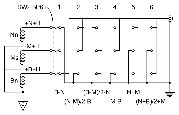
Fig. R.2
Now consider the 6-way humbucking circuit in Fig. R.2, using the same 3 single-coil pickups, again ignoring the tone and volume circuits. The pickups are disconnected from ground, the middle pickup terminals are reversed from those in Fig. R.1, and the same hum phases from each pickup terminal (-H) are connected together a the common connection point, as designated by the triangle with a C inside. Switch 2 is a 3-pole, 6-throw switch which connects one pickup to ground (low output) and one or two pickups to the (high) output. If all the pickups are reasonably equal in electrical and magnetic characteristics, so that the hum signal from each is the same, then every output has hum equivalent to H – H = 0. The resulting output string signals for switch throws 1 to 6, respectively are:
B-N; (N-M)/2-B; (B-M)/2-N; -(M+B); N+M; and (N+B)/2+M
This is the approximate order of tones from bright to warm (for 3 P-90 pickups in a previous prototype), which may change with the pickups and instrument. If the common connection point (triangle-C) is shorted to the ground, then the last term in each expression (-N, -B, -N, -B, M, M) is lost, and so is humbucking. One gets outputs with hum:
B; (N-M)/2; (B-M)/2; -M; N; and (N+B)/2
There is no guarantee that these will have an order of tone that simply increases or decreases in brightness. They will be mixed. For a mechanically-switched system, one can only choose the order of tone for either one of hum or humbucking outputs, but not both. But adding a shorting switch does add more tones.
As a practical matter, it may be hard to tell the difference between a couple of the humbucking tones, leaving just 5 that are audibly different. Or it could just be the tin and tinnitus in my ears. Affordable mechanical switches suitable for this circuit are either the 4P6T rotary switch or the 4P5T lever superswitch. In a commercial Strat-type guitar, either one will often require more room in the electronics cavity under the pick guard that is usually provided. The standard 5-way lever switch on a 3-coil guitar often drops into a deeper hole cut in the bottom of the electronics cavity. To modify an existing guitar could mean routing or chiseling out a larger hole in the bottom of the cavity to accommodate the larger rotary or superswitch. This prototype guitar with a skeleton body and front and back covers does not have that problem.

Fig. R.3 4P6T Rotary Switch Fig.
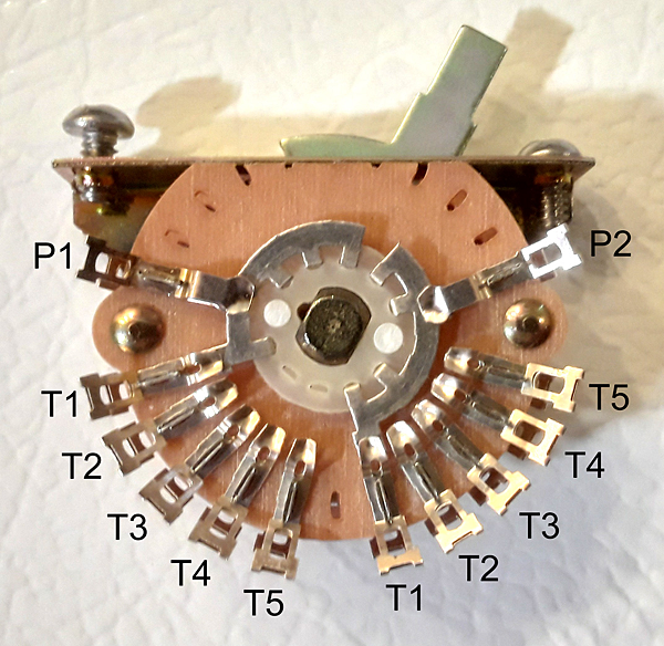
R.4 4P5T LEVER Switch
Figs. R.3 and R.4 show a 4P6T rotary switch and a 4P5T lever superswitch, respectively. The labels Px refer to the pole solder lugs, and Tx to the throw solder lugs. In Fig. R.3, P4 just barely shows and its associated throws do not. The throw labels for P3 on the lower wafer in Fig. R.3, in the lower half of the figure, have lines showing the associated positions of the same throws for P1 on the upper wafer. In Fig. R.4, only the top of two wafers show clearly, with poles P1 & P2, and their associated throws, T1 to T5. The second wafer, with P3 & P4 are obscured by the first. Since a lever switch in an electric guitar is typically mounted as far from the strings as possible, the wafer showing in Fig. R.4 would typically be on the string side of the switch, convenient to the test of the electronic circuit.
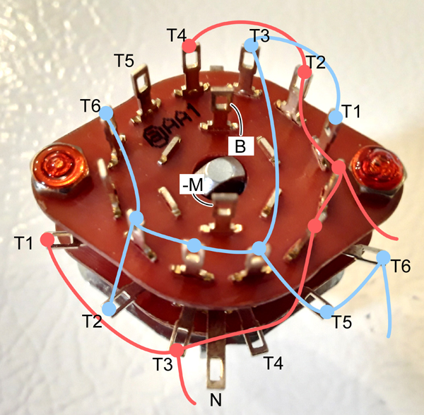
Fig. R.5
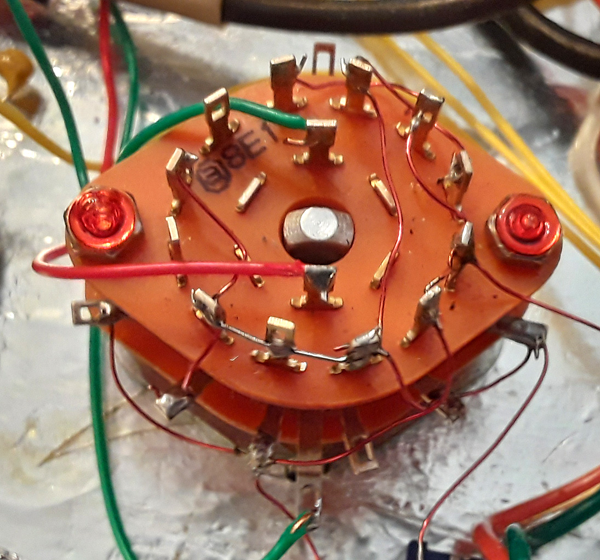
Fig. R.6
It’s relatively simple to convert the circuit diagram in Fig. R.2 to connections on the switch in Fig. R.3, as shown in Fig. R.5. The circuit only has three inputs of string signal, B, -M and N, and two outputs, the high and low (ground). Let the poles and inputs be P1 <—> -M, P2 <—> B, and P3 <—> N, and indicate the outputs by Blue for high and Red for ground. When I first did this, I redrew Fig. R.2 twice again, first to find the shortest wire connections between throw solder lugs on Fig. R.2, then again to make the throws look more like the actual switch. But it can be much simpler and more direct than that.
One can simply mark the tops of the solder lugs for T1 to T5 with red and blue felt pens. In Fig. R.5, all the throw lugs for the B, -M and N string signals are marked with either blue or red dots, according to Fig. R.2. Connect the blue dots together with blue lines, and the red dots together with red lines, and that’s where the high and low output wires go. Fig. R.6 shows how this has been done with 28 gauge solid magnet wire. Magnet wire doesn’t need stripping. The heat of the solder melts the insulation off at the joint. Simply don’t let the wires touch each other, so if the heat travels far enough the wires don’t short together.
Figs. R.5 and R.6 show two red (low) wires and one blue (high) wire going to other parts of the circuit for a previous prototype using three Allparts Vintage Chrome Humbucker pickups with the same switching order as Fig. R.2. Any pole connections and soldered wire pattern that will satisfy the circuit diagram will work. There is more than one, and others may use less wire.
Comments on single-coil pickups for humbucking circuits
There are several essential and desired characteristics for single-coil guitar pickups to be used in this kind of circuit:
- Essential: Two-wire shielded output, with insulation colors coded to indicate hum phases first and string signal phases second. For example, white and black for North-up poles, with black being the nominal negative hum phase, and red and green for South-up poles, with green being the nominal negative hum phase.
- Desired: Nominal negative hum phases are designed to be connected to the common connection point, and should be the outer windings of the pickup coil. The common connection point could be connected to ground through a low-value capacitor to short out the interference frequencies higher than audio.
- Desired: Output connectors.
- Desired: The magnetic direction of poles easily reversible without special tools.
- Desired: Coil electrostatic shielding with interruptions to avoid hysteresis currents due to string signals.
- Desired: Ferro-magnetic poles easily replaceable with different pole shapes, heights and configurations, without special tools.
- Desired: Modular single-coil pickups, conforming to U.S. Patent 10,991,353 (Baker, 2021).


